Honestly on the the 3 design elements :
1 - Copper / Brass thumbtack on the grill way too "1962" trust me. Plus it does not go with your flow using carbon fiber legs at all. Your adding work, and calling attention to something that honestly makes it look more "Garage" built in my opinion.
2 - I am not 100% sure if these are planned for real world production or simply a concept for maybe providing flat packs or something, however you can get grill frames punched out 20 at a time from single sheets of whatever .25" material you want with all the beveling, cross bracing etc... on a CNC machine for probably 20 bucks a pair which would save you a ton of time, materials, and money unless you love the self inflicted pain doing details like this!
It's a grill so I see it as 100% industrial function for protection so I would never listen with them anyway.
By the way I do know of a mass production place super professional that can do the grill frames with state of the art CNC for any possible design you want punched out, and they will do pretty small quantities, with magnets, and all installed already, and yes they are easy to talk to, and located in the U.S. I think they will even put the fabric as a finished product, but that would cost more obviously.
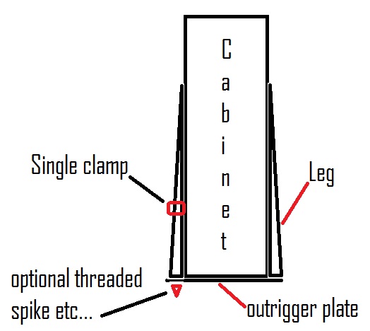
3 - The leg concept is interesting, and I get going for the "Design" element of it, but I will make a serious suggestion here. First you are putting a ton of stress on those bolts holding it to the cabinet regardless of the clamp mechanism, so if somebody tilts this thing, or pulls its weight across the floor I think you risk some type of cracking, or damage at a point in the future. I would highly suggest simply cutting out full "Outriggers" that cross the bottom of the entire cabinet either from metal, or even wood could work, and this will take all the stress off, and give you plenty of surface area to bolt, and place wherever you like into the the speaker. Gravity will do the rest. And then use the "Legs" attached the to the top of the outrigger simply as an ornament with a single fancy clamp you came up with just for audio jewelry to give the design element your looking for, and ultimately save a ton of assembly time.
Then you don't need to try and get the shear strength of bolts like the M3 you mentioned, or anything into the tube itself for alignment, and keeping it from slipping, you just put your tube thru the clamp tighten up so it looks cool, but really has no a critical function at least that your battling with. Otherwise your putting a lot of bank on those tubes to do it all, with clamps holding a heavy speaker in the lateral plain basically "Floating". Again this can be eliminated with a simple cheap, and very effective fix using outriggers like in the photo to pull it off, and you never have to worry about the engineering on this part. Plus it still looks just as cool, and maybe even more robust than before.
Yes I have built many speakers 
Thanks for your input. Let me see if I can address your concerns.
1. Agree with you on Copper rivet. Idea was abandoned, grills are complete.
2.There is no aspiration to mass produce this version. It's a one-of-a-kind that won't get repeated. My motivation is to push at the boundaries of my knowledge and try things I haven't seen/done before. The thread is here to make those explorations public and perhaps entertain or have someone take a little something away for their own project. If it was just about getting 'er done, I'd be listening to them now...eh?
The grills are an example of that, it's a design exercise and won't be for everyone, but then it only has to please me. CNC would be fun, and it's on my bucket list to own, but that's a long and ever changing list...time will tell.
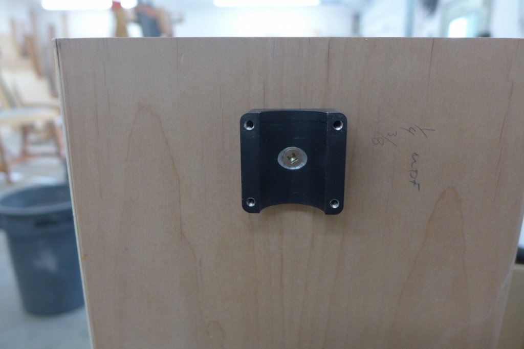
3. You raise a valid concern. I may fly by the seat of my pants, but I didn't get this far along without vetting ideas for functionality. The clamp design was partially borrowed from an existing design that's supporting significant load. Clamping force is more than you might guess and shear strength of mounting fastener is augmented by friction provided by base/substrate interface.
To test your assertion, I half assed a demonstration which I'll show some photos of here. It's not super scientific, but I'll put my stock in real world scenarios rather than conjecture most any day.
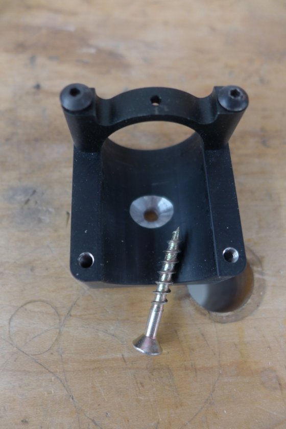
Bases were imagined to work in several ways. A 3mm pilot was drilled in center to facilitate what I envisioned. I drilled the hole to 3/16" and countersunk for #8 flathead screw. Corner holes were tapped for #6 machine screws. Machine screws were engaging threads I base by 3/16" of so. In practice I'd use longer, but it's what I had handy.
I clamped a piece of same sandwich used in speaker side in vice
The bottom insert for tubing is a barbed push in affair, so I bolted a piece of ply to it
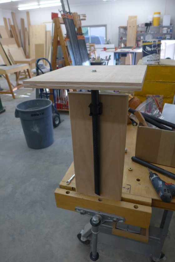
Here's a 25 lb. bag of shot and about 7 lb. in the jar
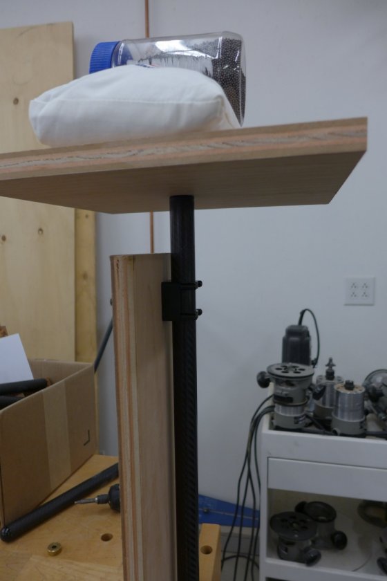
No movement whatsoever. The whole setup is kinda precarious, but I was tired...that's my excuse. As an acid test, I hung my body weight on it but it wanted to rotate or pull the threaded insert out of tubing, but no slippage of clamp. Had I been reading that last statement in a thread I imagine I'd be dubious, but I dare say if I were to rig this up a little better, I think I could stand on a pair of them...no kidding.
I do this for fun, and like most fun, there are moments of woo-hoo! and the inevitable oh, shit!. It's mostly about building the thing and in this case I've put my trust in Danny's design so I can let my imagination run on the construction part. It's my thing, ya know, to puzzle through the minutia.