Erling,
I have a webpage
http://www.rythmikaudio.com/smartQ.html describing the meaning of Q value and its impact on system efficiency. So when people ask me what is the "damping factor" of servo system, I told them, "damping factor" is a metric only meaningful for nonservo system where the transmission loss due to output resistance and speaker cable can affect the frequency response. In servo, I can put in a 4ohm resistor in series with the servo driver coil and it won't change the frequency response a bit. Later I Will explain why this is very important for IB/OB for preventing bottoming.
Going back to the smartQ issue. People ask me what is the Q value of your sub? My answer is "which Q value do you refer to". Because I have 3 different Q values in that servo system. I have a physical Q value (which is Physical Qts and for SW-4-16, it is about 0.

. I also have an equivalent Q value after the servo is applied (for SW-4-16, it is about 0.2), and finally I have a Q value for the frequency response. If we revisit the history, the most basic system has only one Q value which is both the physical Qts value and the frequency response Q value, that is, the physical Q determines the frequency response. Then came the Linkwitz Transform, we have two Q values: one for physical Q value and one for frequency response. That is, the frequency response can be changed. However, this is like asking one person to act as another person. Is the intrinsic character (which is the physical/intrinsic Q) completely gone during this acting? Of course not, if our answer is no, the next question is what intrinsic character is better for this acting? Qts value of 0.2, or Qts value of 1.0. I will always go with the lower Qts value. Because intrinsically high Qts value can induce ringing when the system is under stress. If you are still with me, the next step has become the most important transformation, which is the separation of physical Q and intrinsic Q (or equivalent Q).
Anyone who wants to understand the significance of Q can take out his servo driver (if you don't, go buy one

), and do the following test. Connect the system before you install them into the enclosure. Do not power on, push the cone slightly and feel the reaction from the cone. Nothing. Power the system on, and do the same thing, you "will" feel like the cone is immersed in an oil pot. One of my customers ask me if the nonservo system also has this characteristic. Yes. But our servo increase that damping by a factor of 3x. The oil pot is caused by a mechanical resistance, or one calls it mechanical damping. Speaker is a wonderful product and mechanical parameters and electrical parameters interact with each other. So there is an equivalent effect from one side to another, and vice versa. The electrical resistance of the voice coil act as a mechanical resistance to the system, and hence the damping. That is why Qts is always lower than Qms. To summarize the whole thing, when the speaker driver is open circuit, the only source of damping is the mechanical assembly, which is very minimal. If someone uses a current drive power amp to drive speakers, that is what you will get. The Q value you feel is the Qms value. Very hazardous. If you short the driver coil (only do it when the system is not powered), and do the push test, the voice coil resistance adds to the mechanical damping and add a bit oil damping feeling. This configuration actually emulate the best you can have with a conventional voltage drive amp/speaker system, which is 0 output resistance from the power amp. And the Q value you feel is the Qts value. If you use the servo driver method, the damping feeling is even more obvious. The Q value here is 1/3 of Qts value, meaning 3x more damping. When you do the test, don't push the cone slowly because that only exercises the sub Hz range. Try push a bit faster, but gently to mimic the motion of the signal that the sub will see. Different push speed emulate different frequencies. Now between these 3 different drive methods (current driver, convention voltage drive, and servo drive), which would be better? You know the answer. But they are all based on the same driver with the same physical Q value. That is the meaning of divergence of physical Q and intrinsic Q. And the difference is not just numbers on paper, or a frequency response plot on paper. It is something that we can actually physically feel. The best of all is we can control them independently.
Because of orthogonal Q values in servo system, now I can design them for different tasks without one steps on another's shoe. For instance, the physical Q value is designed such that is will give us the best efficiency curve. In the following is an actual driver that is not designed for IB/OB, just to demonstrate not all drivers can be used for IB/OB. Here is the excursion curve. This curve shows with the amp out fixed at particular max output amplitude, the excursion we would see under that output. It has a Qts value of 0.3.
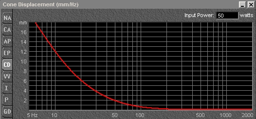
First we notice I only use 50WRMS power to get us this. Second, the excursion at below 10hz is 3x of the region that we really care (above 20hz). That means at full power, we can only get 1/3 or less of what the driver is capable of. The net result is one cannot get sufficient output, which prompt him to crank up the volume which moves the entire curve up and cause bottoming at the sub 10hz region. We cannot design an amplifier so that they can have less output at the amplifier output at 2hz. The entire problem is same as designing a levee. Do you want to design it for a 10hz bottom out or 2hz bottom out? A 2hz bottom out is more rare then a 10hz bottom out. That is exactly what people have experienced. They first experience a 10hz bottom out, then they put in a filter or add more units to take out that 10hz bottom out, and later on experience a 2hz bottom out. When will this end? If we design it for 2hz bottom out, we can not enjoy anything above 20hz (or you have to use multiple units and system becomes very expensive). Now how about this excursion curve.
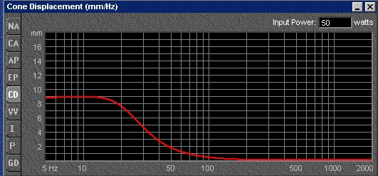
There is no hot spot anymore. This curve has a Q value of 0.9
For those who had bought low Qts driver for their IB/OB and experience bottoming, the solution is put in a series resistor to limit the output below 20hz. This series resistor increases the system's Q value which change the excursion curve from the 1st graph to the second graph. The resistor value is at least same as the voice coil resistance value and one needs to put a heat sink on that resistor as it will dissipate a lot of heat. The extra heat is also caused by the fact the Mms value of low Qts driver is in the range of 250-350g for a 15" and 180-200g for a 12". SW-12-14 has only 100g moving mass for a 12" driver which is almost half. One needs to re-tune the system afterwards as adding a resistor will change the FR in a nonservo system. Also this may not be one-shot thing. That means the user may need to try different values because what works for one driver may not work for another driver. Each time one needs to re-tune. Servo does not have that problem, simply because those three Q values of our system are independent. I can add a resistor without changing the Q value of the other two. As a matter of fact, the FR will be practically the same. So why would we need to add resistor in servo system? In OB/IB, the excursion curve is partially determined by the spider/surround compliance. As anyone would tell you, those two parameters exhibit the largest variation right out the factory and over longer time. We have tried to control it within the best tolerance, but most manufacturers will quote you +/-15% is normal. That means one may need to adjust the resistor value over time. For our servo system, this process will not change the FR and it becomes a very simple process.
To summarize again, there are 3 Q values in servo system, each is designed for its best value. The physical parameter is designed such that it provides max output without causing side-effects. I have a lot of customers asking what is the fs value of your driver? They have associated the fs value of the drivers with the corner frequency final frequency response. This may be true for non-servo systems, but the fs is irrelevant for servo. We need the physical values to play best for our interests and trust me and Danny, we have done that. We will take any challenge. On the other hand, the intrinsic Q value is designed such that it increases the damping of the system so that it can shake off any unwanted cone movement in such a short time that you won't even notice it. And lastly, the frequency response would have another Q that is best suited for your room.
[EDIT] I have to add something to address previous comments. "Is servo worth the extra money?" It is natural to ask this question because most people do not understand the value of our servo technology, but on the other hand, quite familiar with the value of money. So I am here to explain everything about servo so that people can understand the value of this technology and appreciate the cleaner sound it produces. After reading all these and one may ask I have never heard of these and what is your credential and how do I know these are valid arguments. I do have an advanced degree in Electrical Engineering. I can give you completely set of equations, but I guess we listen to music, not equations and numbers. It is the sound quality that is far more important. BTW, when I say all 3 Q values are independent in servo, it is not "literally". But for conditions within our application space, they are "practically" indenpendent. Just for a clarification.