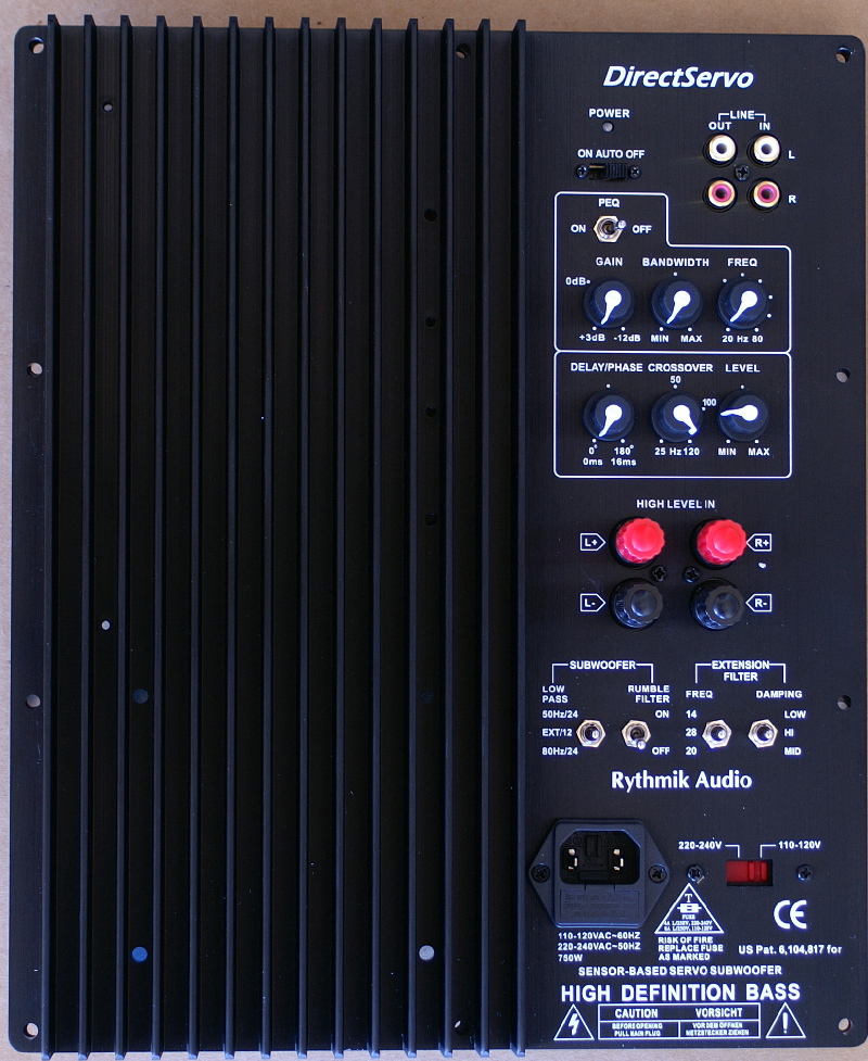
A370PEQ:
On the top is this defeat-able PEQ. The gain level is from 3db to -12db. The bandwidth controls how wide the notch/peak is. Frequency is from 20hz to 80 with each dot position represents 10hz increment. I don't recommend boost below 35hz. But boost above 40hz is ok as our subs
have more headroom there. The first plot is the gain control at 3 different positions: 3db, 0db, and -12db. The frequency setting is at 20hz. the bandwidth is at min.
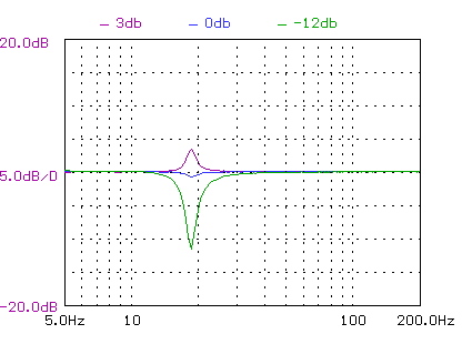
In terms of sensitivity, the 12 o'clock position gives us about -5db attenuation while 3 o'clock position gives us -10db attenuation. In other words, the range between 0db and 3 o'clock is what we will use most.
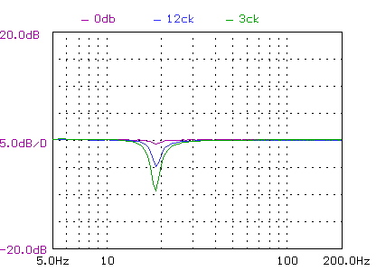
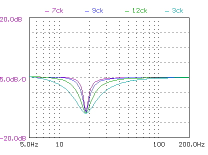
Next is the width control. The comparison is between 7 o'clock, then 9, 12, and 3. I didn't plot 5 o'clock as it is same as 3 o'clock position. The gain is at -12db and frequency is set to 20hz.
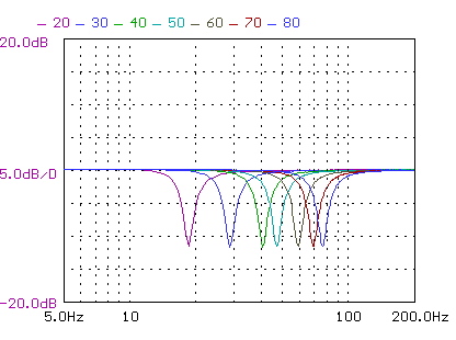
Next is the frequency setting comparison at various dotted positions, from 20hz to 80hz. There is a bit of inaccuracy. But overall it is still very good.
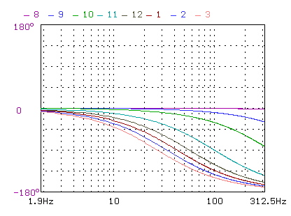
In the middle are our regular controls. The one worth discussion is the phase/delay. It is same as the previous one except I improve the resolution and change the label. The circuit is a simple RC all pass filter. Similar circuit is used for adding delay time (such as those in Linkwitz's all active speakers). That is why I add delay to the label. While the circuit does provide delay, but it will top out at 180 degrees. Theoretically, given a fixed delay, the phase shift should be proportional to frequency. However, this RC circuit will not go beyond 180 degrees. Even though I can cascade more stages, I don't think it is useful. I put in 180 there to stress the fact that the circuit tops out at 180degress. So that 180 degrees is not constant to all frequency. Even if you put in 90degree (at 12 oclock position), that is not constant for all frequencies. To get accurate phase delay, one really needs to first figure out the xover frequency and the reciprocal of that gives use the period. 90 degrees is a quarter of period. Then find the position of that on this dial. Your adjustment range is from 7 o'clock to that position to get 0 to 90 degrees shift, you can more by turning more to the right, but it may saturate at 180 degrees even before you turn all the way to the right. Anyway, a plot is worth a thousand words, and here it is from 8 o'clock position to 3 o'clock position. I only plot to 3 o'clock as there is no change beyond 3 o'clock position.
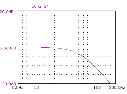
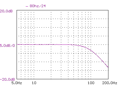
The bottom row has 4 switches. The left 2 are new. One is to replace our 12-24db switch. So this model will replace our 12-24db model going forward. For those with HT receiver and use its bass management, they should get it to middle position 12db/EXT. EXT means the main xover is external. In this case, the xover control knob is mainly for fine tuning. For those don't have HT receiver, or don't use the bass management function on receivers would require the plate amp implement this xover function and that is what this 50hz/24 and 80hz/24 are for. 50hz/24 means the plate amp implement a LP filter with a fixed 12db at 50hz, plus the 12db adjustable knob to make up a 24db total slope. Similarly for 80hz/24. The following shows the FR of this 50hz and 80hz fixed filter.
In either case, one should always use the xover knob in the middle to fine tune the overlap between subwoofer and front speakers. It is more important to combine this control and phase control to achieve the best results. Personally I always use an SPL meter, a test CD (for warble tone), and a spreadsheet.
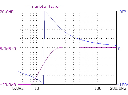
The rumble filter is for vinyl user or those who wants to play louder. It is a 3rd order HP at 20hz.
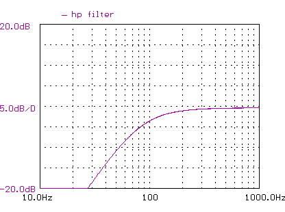
Lastly, the HP filter on the line out.
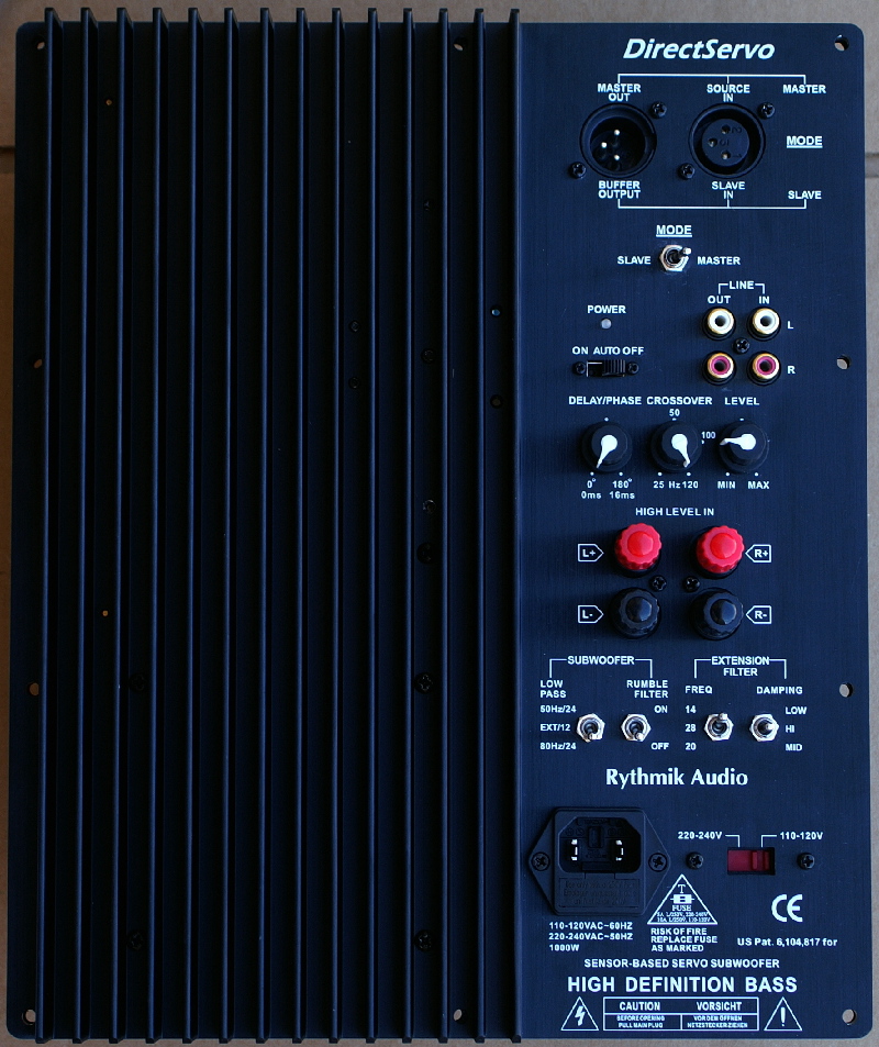
A370XLR:
It has a balanced input and balanced output. However, the balance input is more for subwoofer input only as it does not have HP output. The balanced output is mainly for master/slave configuration. In master mode, the balanced input is just like the other two single-ended inputs, except it does not have HP filtered output. The balanced output goes to another slave unit with the switch set to slave. With this setup, one can precisely control two units to have identical output except phase. In other words, phase control is still functional in slave mode. I believe this is desirable as multiple subs may have different distance to the listener.
The price will be $279 for 4ohms and $289 for 8ohms and 16ohms. This price will be good before summer. I really hope a lot of members can take advantage of it.
Sensor-based servo improves on 3 fronts: 1) the absence of thermal "compression" because the voice coil resistance does not affect the frequency response, 2) The reduction of spider/surround (or mechanical) distortion. The mechanical distortion is worse than electrical distortion because they change over time and become very unpredictable, and 3) better cone control even in the presence of external force. I have published distortion numbers on my web and that gives the impression that I am into low distortion number. My main goal there is actually to show the reduction of spider distortion, not "harmonic" distortion. Among all of them improvement, the one in point 1) is frequency independent and therefore not limited by bandwidth.
The lack of boxy sound from our sensor based servo sub is a result of point 3) above. Anyone building enclosures is familiar with the knocking sound of enclosures with the driver cutout area open, and how that sound becomes more solid when the cut-out area is covered with another piece of solid MDF. Better yet, one can put the head into the opening and listen the echo inside the enclosure. The term boxy sound has been misunderstood as the sound from a box. It is actually more of a box with one wall open so that the reflection/standing wave inside can escape. Therefore a 100% sturdy enclosure cannot get rid of boxy sound because the internal reflection can still escape from the driver's cone. If the cone is not well control, the energy can move the cone and produces a second acoustic wave, and 3rd...
I have been pondering how I can actually measure the improvement of cone control. The other day, I decided to build a device to measure the cone control improvement from our servo. The test enclosure has two chambers sharing a dividing wall. A driver emulating the reflection from the wall is mounted on the dividing wall is called "reflectance simulation driver" (RSD). One of the chambers is completely sealed and the DUT (15") is mounted on an outer wall of another chamber (sort of like a bandpass enclosure with the vent replaced with the DUT). The purpose is to measure how much DUT moves relative to the RSD's cone movement. The smaller the movement from DUT, the better. It is an indication that the cone can resist better to the standing or reflective sound waves. We compare the servo setup to the nonservo setup and plot the ratio of the two and we get:

The middle horizontal center line is 0db, which means no improvement at all. The best improvement is indeed 3x in amplitude (or 10db, 10x in power) and diminishes above 60hz, but to my surprise, that it does not go to zero until 500hz. Although I show the result for 15", the improvement from the 12" driver is also similar. Can a nonservo sub achieve the same improvement? Sure, it can, but with 3x magnet size (in order to increase the B value by 70%) because this excellent cone control is a result of 0.28 Qts when loaded with enclosure (not free air). Even if one actually uses a triple size magnet to achieve the same Qts value, the side effect of stall will come into play to signifcantly reduce the output around the resonance frequency fs. So much so it reduces the output by up to 5db (or 3.3x in power) around fs frequency.