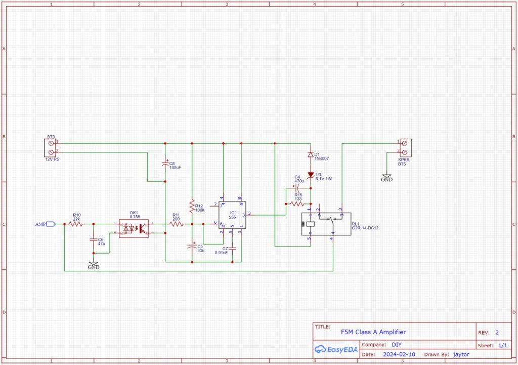
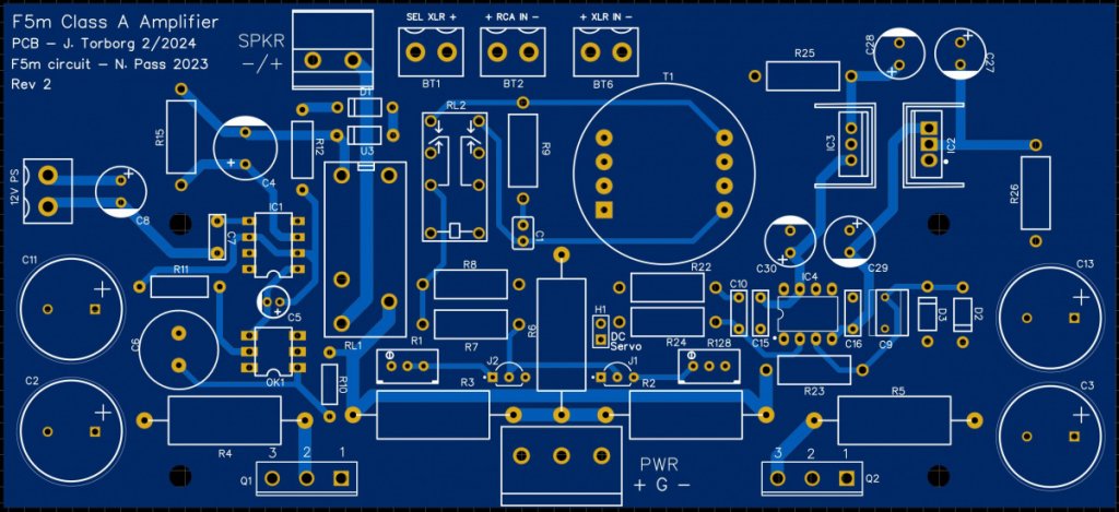
In case anyone is interested, here is the design I am building for the F5m boards. I ended up doing a new PCB because the footprint I used for one of the relays was incorrect (one of these days, I will learn my lesson to not trust the community-provided footprints

).
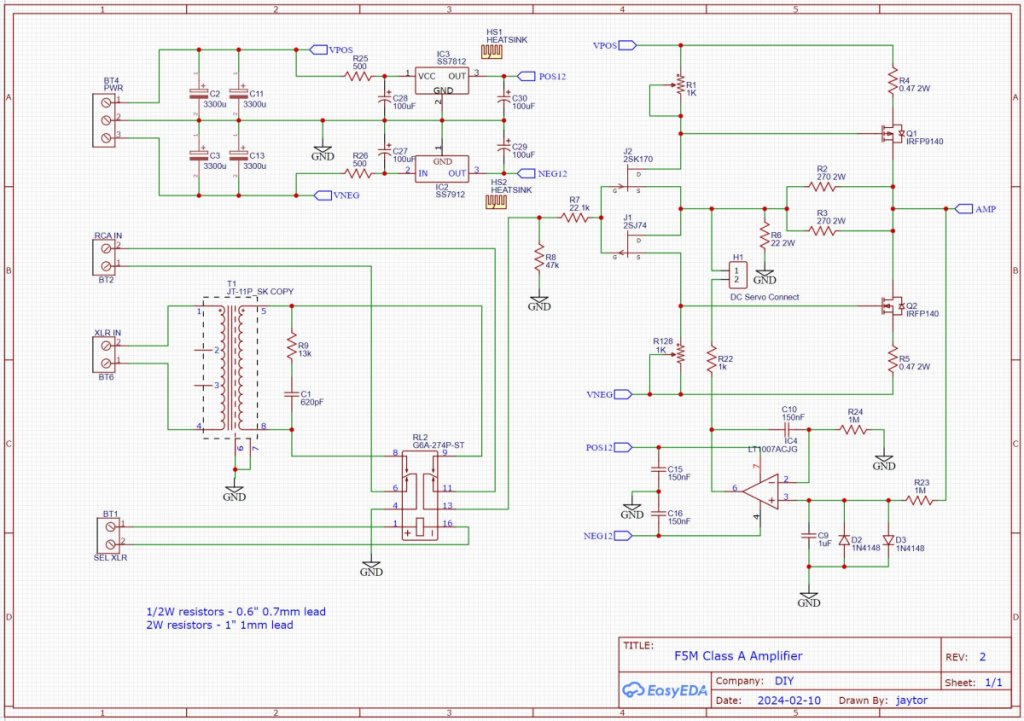
I took the opportunity to make a few improvements to my initial design. I beefed up the terminal block connectors for the main power and speaker connectors, changed the op-amp to a single (instead of a dual) that has a bit lower offset current, and I added a couple protection diodes on the input of the op-amp to make sure the input never gets too large (which could be an issue during power on and off).
The design assumes a main power supply that is roughly +/- 24V. It also uses a second 12v power supply for the DC protection circuit and for switching the input relay to balanced. I plan to use a small AC/DC converter module connected to the main power switch. This will turn on and (more importantly) off much faster than the main supply, so that the outputs will be disconnected immediately on power off.
A switch on the back panel will connect the 12V supply to the input selector relay to select balanced inputs.
I am still going to finish building the rev1 board to test out all the circuits before I send this version out for fab.