Crossover assembly 101

0 Members and 1 Guest are viewing this topic. Read 321281 times.

Shives

  • Jr. Member
  • Posts: 250
  • I like French fries
Re: Crossover assembly 101
« Reply #280 on: 4 Apr 2021, 06:24 pm »
Happy Easter!!

Looking for a good program to make nice schematics, but ended up just doing it long-hand written out a bit better... Maybe.

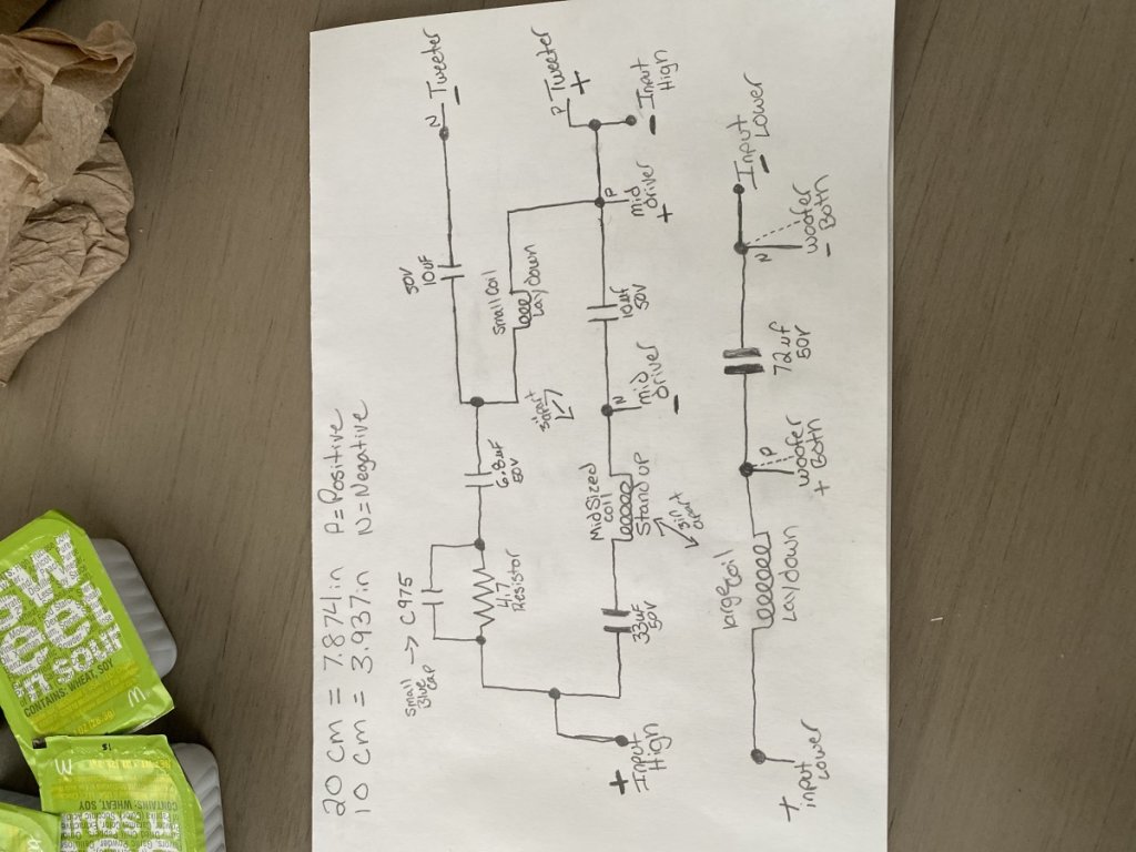
It will be for the  JAMO classic 8. This is what I’m gathering from the photo and supplied photo. Been years, but anyone can check my work, please. I’m happy to explain if needed, or answer questions. Also welcome to send me a PM of you need assistance or have a question about placing the components .

In a nut shell, make sure the inductors are not laying flat. If so, then make sure they are about 8 inches away from each other. Other wise, lay big one down, make sure mid rolls into, and smaller one lay down. This will mean you’ll only need about 4 inches apart. I don’t have the components to lay out, but again welcome to work something out if you need assembly help.

I tried to Mark things more to standard (if I recall right) as well trying not to go over head and allow you to see better where things hook up. If that drawing you gave me is right.
Dotted lines are just trying to show second woofer wire location. Again, both lower woofers share connections. Both are hooked same way, same spot. The mid and tweeter share a little then break out.

Try and run 1 negative line from terminal to speaker. You can cut the jacket off the wire say about 2 inches where needed then solder to wire without cutting. It keeps the chain solid! Sorry being yelled at this second. Have to run!
Happy bunny day


Shives

  • Jr. Member
  • Posts: 250
  • I like French fries
Re: Crossover assembly 101
« Reply #281 on: 4 Apr 2021, 06:37 pm »


Wow... no matter how I upload, it keeps getting turned. Apologies.

corndog71

  • Full Member
  • Posts: 1670
  • Some people call me Rob.
Re: Crossover assembly 101
« Reply #282 on: 4 Apr 2021, 09:39 pm »


I redrew it so it made more sense.

Nebander

  • Jr. Member
  • Posts: 4
Re: Crossover assembly 101
« Reply #283 on: 12 May 2021, 11:46 am »


I redrew it so it made more sense.
I just finished another one of the Jamo Classic 8 crossovers. One component, one separation, and a lot of wires later the finished speaker sounds so much better!

The jaggedness and saw-like quality are totally gone and the sound is super smooth and natural. Even when playing these speakers in stereo, the sound image is much fuller and live-like on the fixed speaker side.

Thank you guys for the input! I fully recommend the upgrades to xovers.

dbog

  • Jr. Member
  • Posts: 5
Re: Crossover assembly 101
« Reply #284 on: 19 Jun 2021, 06:02 am »
I'm not sure what the problem is, but I don't see any images of the process outlined by Danny on the crossover assembly.  Is there a setting that I need to change on the site?  I'm using a Chromebook if that has any bearing on the issue.  Thanks

Hobbsmeerkat

  • Industry Participant
  • Posts: 2529
Re: Crossover assembly 101
« Reply #285 on: 19 Jun 2021, 02:15 pm »
When Danny switched his server, all of his pics stopped working properly, unfortunately.

dbog

  • Jr. Member
  • Posts: 5
Re: Crossover assembly 101
« Reply #286 on: 19 Jun 2021, 05:27 pm »
Thank you.

chenson

  • Jr. Member
  • Posts: 15
Re: Crossover assembly 101
« Reply #287 on: 2 Jul 2021, 07:14 pm »


Hello everyone! I’m new to this and not an engineer - I’m more of a visual thinker. I like to sketch out problems as I work on them. I’m trying to put together a crossover for an NX Studio build. Is anyone able to confirm this sketch? Does it look right? I’m especially uncertain about that bundle in the middle where some negatives and a positive connect to the same point (see the question mark). I’m not confident in my ability to interpret the crossover schematic included with my kit and the photos people have posted have been helpful but a little blurry.

Thanks!

Hobbsmeerkat

  • Industry Participant
  • Posts: 2529
Re: Crossover assembly 101
« Reply #288 on: 3 Jul 2021, 12:31 am »
Yup! That's correct! :thumb:
Its just weird because the polarity is reversed vs the woofer and that throws a lot of people off.

chenson

  • Jr. Member
  • Posts: 15
Re: Crossover assembly 101
« Reply #289 on: 3 Jul 2021, 12:48 am »
Thanks! That makes sense. I had a vague idea that it was an intentional phase flip. I have a preamp (a ModWright LS100) that changes the phase so I either have to manage it with DSP or flip my speaker wire inputs. This layout made me think of that.

I could leave it there… I’m happy that it will work… but I’m curious and I’d like to learn. Why the phase change? Is that a characteristic of all crossovers? Or is it just this particular tweeter needs a phase change? Or does it have something to do with the timing between the tweeter and the woofer - similar to how you might adjust the integration of a sub with the phase?

corndog71

  • Full Member
  • Posts: 1670
  • Some people call me Rob.
Re: Crossover assembly 101
« Reply #290 on: 3 Jul 2021, 01:20 am »
That’s a cool drawing.  I like to draw out my designs too.

This was an amp circuit I reimagined.


chenson

  • Jr. Member
  • Posts: 15
Re: Crossover assembly 101
« Reply #291 on: 3 Jul 2021, 12:36 pm »
Very nice drawing. It’s always interesting to see how people draw their projects or sketch out their problems. In my day job I work as a UX designer and I sometimes run workshops with software engineers and project managers. Some of the workshop exercises involve a lot of quick sketches. When people can get over their fear that they can’t draw the results are almost always fruitful. I’m less technical myself so I find complex detailed technical drawings fascinating.

cjsailer

Re: Crossover assembly 101
« Reply #292 on: 10 Jul 2021, 03:50 pm »
Hello, hopefully someone can peer review my crossover layout for the NX Otica.  I'm mostly wondering about the orientation of inductors relative to one another.  I don't know what the field direction is on that laminated inductor in the lower right of the image.


Chewbacca

Re: Crossover assembly 101
« Reply #293 on: 10 Jul 2021, 04:46 pm »
Hello, hopefully someone can peer review my crossover layout for the NX Otica.  I'm mostly wondering about the orientation of inductors relative to one another.  I don't know what the field direction is on that laminated inductor in the lower right of the image.

Hi cjsailer! Everything looks correct to me, but I think you may have an issue with the bottom orientation like you suspect. To the best of my knowledge the field orientation for the iron core follows the coils around. You may have interaction between your large foil and the iron core. Also - I don't think I'd want that little tang of iron sitting right next to the foil either. Magnetic metal right next to the foil inductor spells a no-no in my head.


For others reference I'm going to reinsert this here as well:


I believe you have the equivalent of #4/5.

cjsailer

Re: Crossover assembly 101
« Reply #294 on: 10 Jul 2021, 05:20 pm »
Thanks Chewy, I think I'll stand that laminated inductor on end (vertically) and move it close to front by the positive in lead.  There'll be plenty of space between the two inductors then.

mlundy57

  • Industry Participant
  • Posts: 3561
Re: Crossover assembly 101
« Reply #295 on: 11 Jul 2021, 01:13 am »
Here's how I built it


E-Zee

  • Industry Participant
  • Posts: 149
    • Diy speaker resources and crossover assembly services
Re: Crossover assembly 101
« Reply #296 on: 12 Jul 2021, 05:28 am »
The NX-otica is moderately complex and being open back with skeletonized support shelves, splitting the components to two boards is less than ideal. Further complicating it are the multiple versions existing. I dont know all the revisions but some earlier versions had 4 inductors.  Current with the newer tweeter has 5.
 I like the idea of mounting the large iron-core inductor on the underside of the bottom support shelf. That would give more space on main board, remove some potential for crosstalk between inductors, and the iron core in underside would be mostly hidden.  Here's pictures of the Otica I'm working on designing layout for today.  I haven't settled on anything but the right side I think is problem free. Im still playing with a couple variations on the left side inductors.  Debating Ironcore laying down vs standing up. Debating switching the iron core with the other inductor on left side.  Currently the stagger left to right and max space left to right is the best I can come up with for today.   Sometimes sleeping on it helps.  Hopefully tomorrow I'll wake up fresh with a good idea. 


Here is an earlier conductor variants as I was evolving through the process.  This is one of those situations where with all 5 inductors on board you must pick the least harmful layout as there will unavoidably be some minor conflict. There's no ideal solution I see without removing the iron core from the board.  Pull it off and mount it on the cabinet somewhere else and I think you are conflict free.


Chewbacca

Re: Crossover assembly 101
« Reply #297 on: 12 Jul 2021, 01:56 pm »
Hey E-Zee, I've been working on the same layout for a little bit of time now, and I came across the same issue as you with the Iron Core.

This is my finalized layout that I ended up going with (don't mind the mess):


There may be some interaction between the larger inductor on the tweeter circuit and the iron core, but at this point it's a battle of the least amount of evil and I think I should be good.

I'm going to wrap the one positive lead you see around the paired resistors and solder that to the tube connector. These are the only leads from the positive terminal.

On the negative terminal one lead will go straight out and catch the tweeter circuit. The other lead will go under the sonicap bundle and catch the smaller sonicap on the negative lead to the woofer circuit.

Should be pretty clean all said and done. I wanted to have it all mocked this weekend, but ran out of time. Maybe have it fully together this week. I just don't want to solder any leads on that go to the speakers yet, because I don't know exact lengths without the cabs being done.

I think the tweeter circuit alone turned out pretty nice (still need to trim a couple pieces... want to wait until after solder):


Badd99

  • Jr. Member
  • Posts: 87
Re: Crossover assembly 101
« Reply #298 on: 13 Jul 2021, 07:07 pm »
Hey guys can someone give me the dimensions of their board they are using for the nx otica? I have all the kits still in boxes as I don't have my music room dine yet but would like to do the crossovers now. Thanks!

Also - for the nx otica I'm planning to change the tweeter inductors to foils and use path resistors.

Anyone thinking about changing out the erse cap on the tweeter?

I also am going to bypass the sonic caps in the tweeter and mids with a vcap odam 0.1

Chewbacca

Re: Crossover assembly 101
« Reply #299 on: 16 Jul 2021, 02:05 pm »
Hey guys can someone give me the dimensions of their board they are using for the nx otica? I have all the kits still in boxes as I don't have my music room dine yet but would like to do the crossovers now. Thanks!

Also - for the nx otica I'm planning to change the tweeter inductors to foils and use path resistors.

Anyone thinking about changing out the erse cap on the tweeter?

I also am going to bypass the sonic caps in the tweeter and mids with a vcap odam 0.1

Hi Badd99,

Unfortunately I don't have my boards with me, but a took a couple minutes to quickly draw something up based on some dims I have on my phone:


https://www.audiocircle.com/index.php?action=gallery;area=browse;image=227019;size=huge

I'd probably do something like 10" (back width) 5.25" (front width) 14" (depth).

Basically:

Widths: size of the shelf - .25"x2 (dado) - 1"x2 (no-rez) - tolerance

Depth: size of shelf - .25" (dado) - tolerance

Hope that helps! :thumb: