Hi Folks,
I have a turntable wall mount - with mods added (of course) - that solves some of the traditional problems in a slightly unique fashion. It won't be needed for everybody and may not appeal to everybody but it goes a ways toward solving problems that are quite common in a lot of home audio environments. I do not have any usable drawings or plans - but many DIYers may be able to use the concepts and design around their particular needs/desires - to come up with something as good or better. First some talk about the issues at hand from the former mechanical engineering kool-aid drinker. There are two main areas of concern:
1) Footfalls: Typically a problem on anything less than a concrete floor. It is annoying in the extreme to have skips or flub-flubs arise from someone else walking into the room, or you getting up to grab the remote or the album jacket. And then, if you are playing at sufficient* volume - it's going to happen - you may be inspired once in a while to get up and move a little! (*sufficient is the word I'll use for what some folks would call too durn loud

)
2) Audio feedback. Anything less than a concrete floor mounting and you probably have this at some level. Joist floors are acoustically stiffer than walls but not a whole lot. Neo describes them, accurately, as springy. Particularly if you employ subs you may hear the effects, and at 'sufficient' levels you could trigger genuine self-sustaining feedback at very low frequencies. Below self amplifying, the relative level at any one frequency of this feedback does not change. Playing things more quietly may succeed in that it drives any waveform mis-shaping that may be happening down to a level that's harder to detect by ear.
The overall goal, is to limit the energy (amplitude at frequency) received at the turntable plinth. Many turntables have sub plinth internal suspensions that are pretty good - for the audio feedback area of maybe 40 Hz and up - making the problem anywhere from less to quite un-noticeable for many systems. For footfalls and lower LF problems there are two major approaches:
A) Mass: A large amount of mass in the stand, together with the floor spring rate can drive the natural frequency down quite a bit. And, a large mass limits the amplitude of the response, by requiring more energy to drive it. (this of course is why concrete floors are so ideal - large mass and very low springiness)
B) Decoupling: Again the very best decoupling is simple solid mounting back to earth - and almost the only solution for footfalls. Next best, for audio feedback, is to drive the natural frequency of the suspension system to well below that of the audio reproduction. The technical explanation is that any system is most efficient at responding to energy delivered near its natural frequency. If the natural frequency is driven significantly low then it really can't respond well to anything very much above that. (Crude example: Friend sitting on a swing. You step up and try to "shock" them by yanking quickly on the chains halfway up. Doesn't work too well. They just sort of start to swing a bit at the natural frequency of the swing and most of your energy did not do very much.) Commercial isolation stages usually are based on mechanical linkages that do just this sort of decoupling and then sometimes add some passive or active damping. (I have worked with Minus K-Vibraplane units in my (non-audio) professional life - and they do measure up as pretty magnificent - but I have thus far considered them too spendy for home use)
So my story starts very similar to many folks. I have a normal joist floor and normal 2x4 walls. I put up with the footfall thing for many years - then added a wall mount. (simple Target TT-1) Footfall relief was immediate and dramatic. Most walls are very stiff in the vertical direction. (mine maybe a little more so given that it sits on foundation about 3 feet down from the turntable) Even walls in upper floor rooms will usually be significantly stiffer in the vertical direction than the joist floor.
Next, I added some well integrated subs and started noticing serious audio feedback - even to the point of self-sustained feedback at maybe 15-20 Hz or so, at 'sufficient' volume levels. Experimentation rather quickly showed that the wall and shelf was responding in an in-out fashion to the LF audio. At those frequencies, with maybe 50 foot waveforms, you are really more simply than ever raising and lowering room air pressure - and standard 2x4 walls are even more springy than floors in that direction. I needed very specifically to decouple from wall horizontal motion - so that the wall is free to wobble and the turntable stays still - at frequencies significantly upwards of the isolation natural frequency. The following assembly is what I came up with to do that. (essentially a much more domestically friendly and appealing variation on the old suspend the turntable from the ceiling approach)
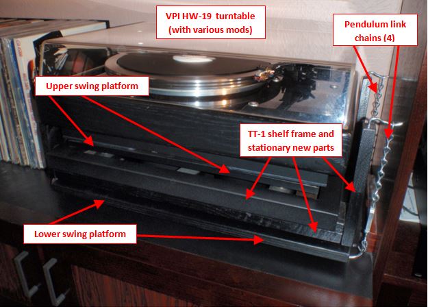
Fig. 1 - Turntable isolation stage - The Overview. (exploded views in upcoming figs) In addition to the basic low natural frequency mechanical goal, desires were to come up with an assembly that was: A) Reasonably compact B) Appeared to be resting on the cabinet below C) Still allowed clear access to the turntable above the dustcover bottom edge.
Fixed parts bolt onto the bottom of the TT-1 shelf and extend 4 towers up vertically. The pendulum chains are approx 9 inches long, giving a natural swing frequency of about 1 Hz. The chains suspend the lower swing platform. The upper swing platform is directly coupled to the lower by large tubes reaching up through the shelf bracket internal open spaces. The upper platform carries the turntable and is free to float approx +/- 0.4 inch in any horiz direction.
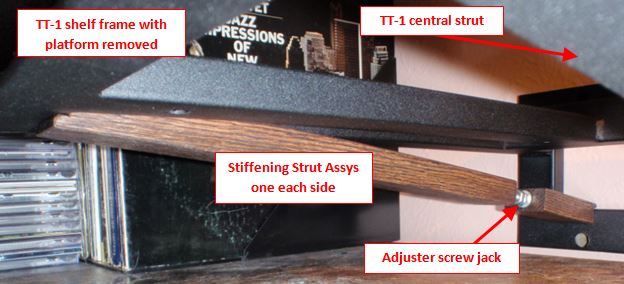
Fig. 2 - TT-1 shelf frame and first mods - underside view - The TT-1 model has only the one slightly diagonal strut in the center to stiffen the horizontal shelf frame. The mass of all items I was planning to add would push close to the approx 55 lb design load limit. I constructed 2 additional strut assemblies that could be installed to help carry/stiffen the load. These strut assembly's positions can be seen more clearly in fig 4)
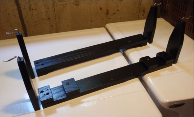
Fig. 3 - Fixed parts and towers - Lower assemblies needed to be constructed to work around the stiffener struts. Screwed and glued interfaces in oak. Top hooks for the pendulum chains are just unbent eye screws. At this point found that a coat or two each of india ink and polyurethane made for a finish approximating the old HW-19.
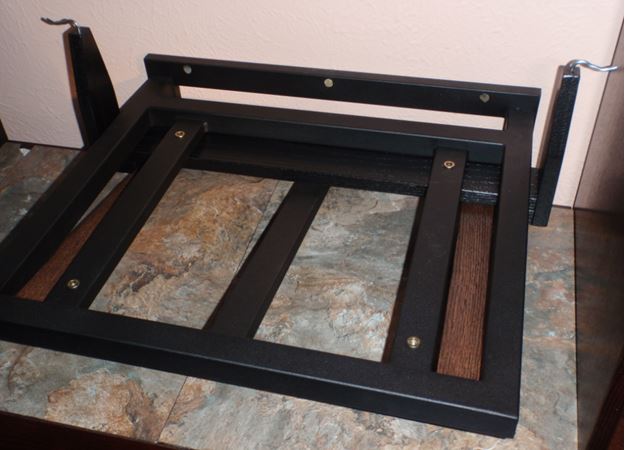
Fig. 4 - Stiffening struts and rear tower assembly in place - Lower parts of tower assemblies bolt up to the inserts originally used for TT-1 shelf mounting/leveling.
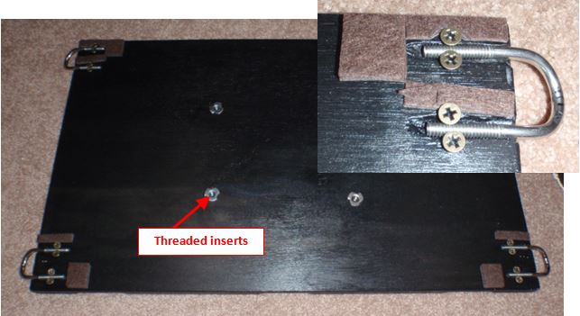
Fig. 5 - Lower swing platform - bottom view. Inset shows the crude but effective attachment of the pendulum chain lower anchor u-bolts. U-bolts were bent slightly in the upward direction to make a more localized spot for chain ends to settle.
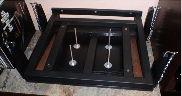
Fig. 6 - Lower swing platform in place. Each pendulum chain assy has a small turnbuckle, allowing leveling and relative tension adjustments once the full load is in place. Coming up from the platform are threaded rods that will be used to help attach the upper platform.
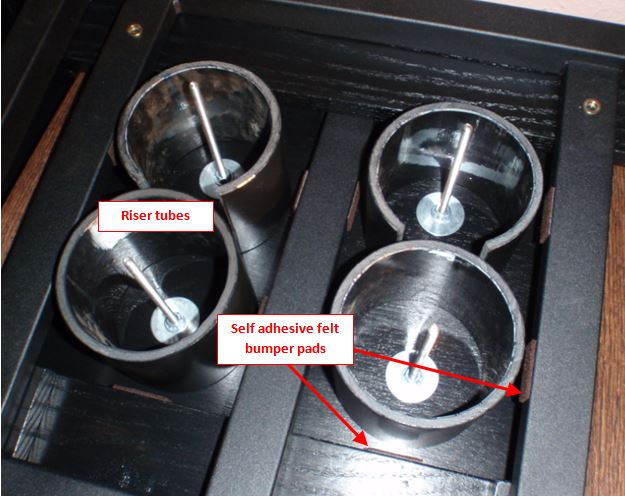
Fig. 7 - Riser tubes and bumpers in place. ABS plumbing (sewer) pipe was used. Tubes were cut to uniform length with a miter saw blade clamped on wood blocks at the desired height off of a table top. Space available meant 2 tubes needed to be cut into C-sections.
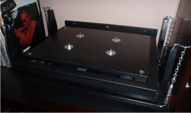
Fig. 8 - Completed assembly, minus turntable. Riser tubes place upper swing platform about 1/4 inch above TT-1 frame. Threaded rod tops poke up into available space in bottom of turntable.
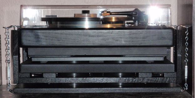
Fig. 9 - Straight face/plan view of completed stack-up.
If you'll give me some time to catch my breath, I'll write up some notes on how I measure audio feedback levels and talk about what this rig does in that area. (It is keeping me real happy - and even dancing around once in awhile!)
Cheers, John


