Dribs and drabs...
I started cutting “real” chips. The assembly plan is to glue the sides to the top and bottom pieces first. So I routed the top and bottom pieces as I figured these would be the easiest to do. I decided to do the routing in a 3 step process - the actual routing is 2 steps; first is about a 3/8” cut and the second is just under 11/16”. The 3rd is a trim cut on the table saw to get the 3/4” + just under 1/32”. I did the routing with an extended guide that was clamped in place on the table’s guide rail. This facilitated the use of 3/8-ish” plywood spacers for making the 2 router passes.
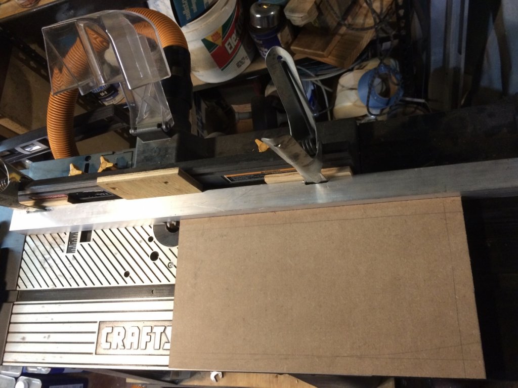
As a aide to making the routing passes, I marked the “outside” of the panel, as seen in the picture, with an outline of where the cuts were to be made. A nice thing about the design I am using is that none of the pieces will be “handed”. That is the top is the same as the bottom, as are the two sides, so I don’t have to worry about cutting a “left” or “right” pieces.
The extended guide for the guide rail on the router table is intended to aid in routing the long side, and front panels. It also works will for the shorter pieces. This is just a 1.5”x1.5” square aluminum tube. I cut slots in it for spring clamps and cut a notch for the router bit. The notch is about 1/2” high so the router bit, set for a 3/8” deep cut, would clear, and there would still be an uninterrupted surface to slide the panel on. The backside of the tube is cutout to match the vacuum hole in the table’s guide rail. If anyone is interested, I cut the aluminum using a Dremal grinder set on a slow speed, using a RotoZip down spiral drywall cutter. I used tube I had on hand, which is 1/8” thick. If I was buying a piece just for this, I would have gone with the 1/16” thick tube as that would be easier to cut.
By making the final cut on the table saw, I figured the width of the routing pass (the 3/4” direction) can be less than accurate and I can concentrate on having a good, clean depth of cut. While this may take a bit more time, it went quickly for the top and bottom pieces.
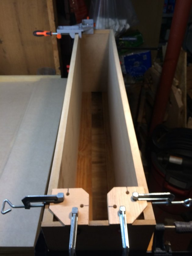
I did a dry fit with the actual side panels.
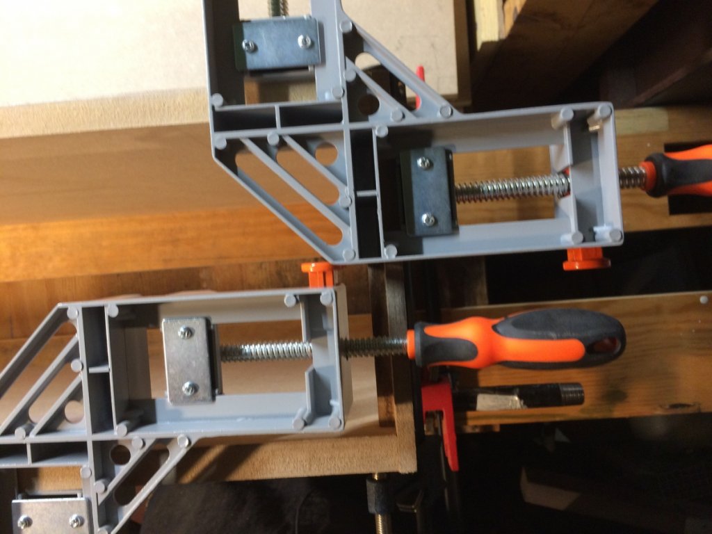
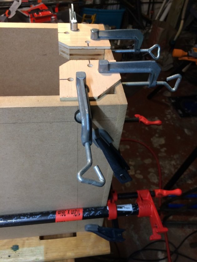
I am really liking the 3rd Hand clamps I made. The corner clamps I bought will be good for gluing a corner but my clamps are easier to use.
The routing and trimming seems to have come out well, complete with a slight overhang of the top/bottom pieces with respect to the side pieces. And the internal width at the clamps is 7” as per Danny’s plans.
Dry fitting - Always a good thing. It seems that no matter how much I check and measure, I miss something. In this case I found that one of my top/bottom panels was not cut square. I know I checked this, but missed it. Turns out, that of the 4 panels I cut, 2 were off.

I lucked out, though. They were off on the high side so they could be trimmed square(er), which is a big PIA.

The other thing I found was that the side panels are really flexible and there is no way to get a side to side measurement at any place other than where the clamps are. That dimension will truly be set by the internal braces and the front panel (with the way I plan to do the assembly). The back panel will need to be custom fit, the way I see it now.
There will be more dry fitting as I get other pieces routed.
Just one other note...
With respect to the corner clamps I bought, the quick release button is on the wrong side and interferes with having 2 clamps close together. Something to watch out for in buying clamps... And I have to wonder if the people who design and build things actually ever uses them....

Why did they not put the buttons to the inside of the clamp angle? Ugh!