Vinnie,
Have you quantified a 'full' break-in time? 150, 300, 500 hours?
Also, might there be an RCA>BNC adapter included?
Hi jriggy,
Hard to really come up with an exact time, but after the 1st 100 hours, you are > 95% there.

A BNC-to-RCA adapter is included for non trade-in orders. If you are trading in your LIO DAC 1.0, then keep
your BNC-to-RCA adapter... or let me know if you lost it and I'll give you a special price on a new one.

Like others, the difference is recognized immediately with separation of instruments being most pronounced. Even more substantial is the improvement with some of my higher quality DSDs.
Just wow...I really can't believe what I'm hearing.
Thank you so very much Vinnie for being a visionary and bringing products of this quality to the marketplace.
Thank you for posting your initial impressions, Mike (and everyone!!!)

I snapped a few cell phone pics of a LIO DAC 2.0 on the workbench:
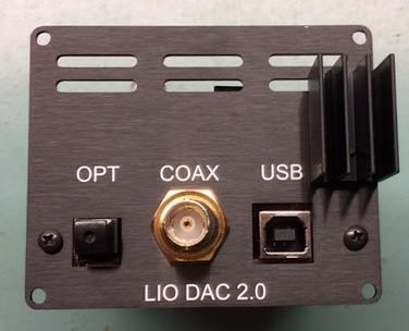
[There is a linear voltage regulator behind the heat sink that does the lion share of reducing the input voltage from the ultracap banks, so it does get fairly warm]
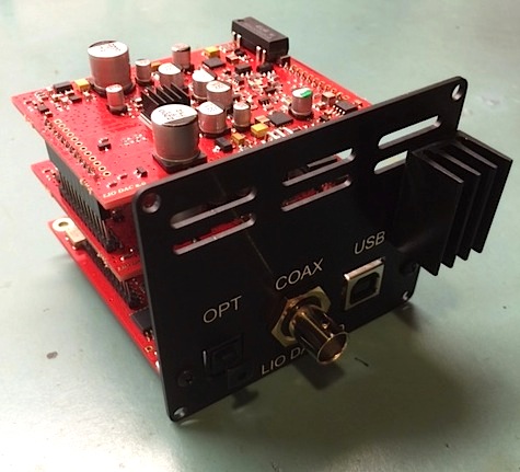

[Side view of the LIO DAC 2.0's neat and tidy 3-PCB stack. The little heat sink on the top is for the LEFT D/A chip. There is also one on the RIGHT D/A Chip, which is located on the middle-level PCB. The two transistors coming off of the top and middle PCBs are used in the Class A analog output stage and get warm, so they are near the ventilation slots on the rear panel]
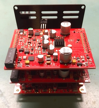
[Here is a better view of the top PCB for the left channel. Pretty much the entire left half of this PCB is the discrete Class A analog output stage, and linear voltage regulators for the output stage and D/A chip. You can also see the mute relay on the bottom left side of this pic. This is a very silent reed relay, so you shouldn't hear audible "clicks" during song changes of files that are of different sample rates.
The mid-level and top-level PCBs are the same (except one is configured for LEFT channel, and one is configured for RIGHT channel).
The bottom PCB is for the digital inputs, as well as the XILINX FPGA, oscillators, re-clock circuit, PIC micro (control firmware), linear regulators for various 5V, 3.3V, 2.5V, 1.8V, etc.]
Vinnie