For quite some time now (I think 2+ years qualifies) we've been modeling, prototyping and modifying various buffer designs. In fact one of my key goals for 2016 is the release of a buffer product. Time is indeed running short to accomplishment that.
Sooner or later you have to drive a stake in the ground, stop noodling around endlessly, commit to a design and produce it. That time has come for our buffer.
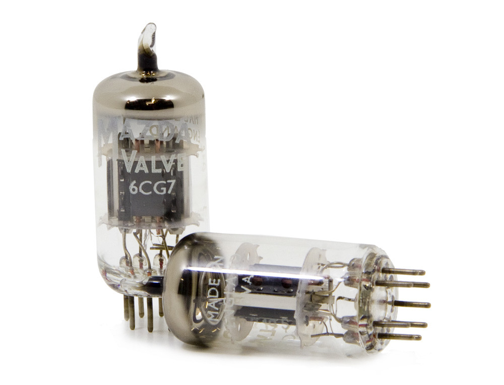
One of the key decisions that's been made is whether to go solid state (JFET) or tube. TUBE it is! In fact the 6CG7. For the tubular among you the 6CG7 is the smaller 9 pin version of the venerable 6SN7 octal tube.
A key design criteria for our tube buffer is we wanted to fit the whole thing, including the power supplies, inside one of our existing 3x6x8 inch extruded aluminum cases. That meant no big black honk'n transformer riding on top of the enclosure either. Everything inside. Except the tubes themselves of course. A pair of 6CG7 tubes will be standing up through the case. Figuring out how to accomplish that took a fair bit of time. We are using a pos/neg voltage doubler to produce the main split voltage power for the tubes along with 3 separate small low-profile semi-toroidal transformers mounted on a board along with the rest of the power supply circuitry. There will be 2 separate boards, the buffer board and a power supply board.
Another key design criteria was the elimination of soul-sucking coupling caps from both the input and the output the buffer. To accomplish this the tubes are powered with a split voltage +/-125 VDC supply rather than a single sided supply. Configured as cathode followers each channel has a pair of triodes connected top to bottom with the output coming out between them at essentially 0 volts. A servo circuit is included to ensure the elimination of any remaining DC offset. In the unlikely event that the DC offset gets our of bounds there's a DC offset detection and safety isolation circuit that will disconnect the buffer output. This circuit also avoids any bumps or thumps during power up and will only connect the buffer outputs once the DC offset on the output is minimal and stable.
Since eliminating coupling caps required a DC offset eliminating servo we ended up with a high quality op amp input stage using the LM49720 op amps. Hence the reference to this being a "hybrid" tube buffer. I love the LM48720's having used them before in several designs including as upgrades in a DAC I've been using. The input stage takes direct DC input and is nominally unity gain although the design does provide for switching out a couple of removable plug-in resistors if you want to boost the gain for any reason. All of this further complicated the power supply since now we needed a split +/- 15 V supply for the op amps. It's all in there!
Barring any surprises (those never happen...not!) I expect to have a near-final prototype running later this month (October) and final-final prototype in November for release by year end. I'll post some pics as soon as we have something presentable but imagine one of our LDR3.V2 preamps with a pair of 6CG7 tubes sticking out the top and you'll get the visual gist.
To be clear, this hybrid tube buffer will NOT fit inside next to our LDR preamp board in our existing preamps. The tube buffer requires additional real estate. I do envision a possible combined buffered preamp in an single package but it will be twice the width of our existing V2 preamps which means ~ 3" tall by 12" wide by 8" deep.
Watch this space!