Crossover assembly 101

0 Members and 1 Guest are viewing this topic. Read 321241 times.

nwviking

  • Jr. Member
  • Posts: 3
    • Timbra
Re: Crossover assembly 101
« Reply #300 on: 16 Jul 2021, 04:24 pm »
Hi All! New here and doing my first GR Research build of the X-LS Encore. I've done 2 other non-GR DIY builds but am still learning about crossovers. Hoping to get a set of eyes on this layout before I solder. I looked through this thread and others but couldn't find any reference with the same parts I have. I got the Miflex Copper Bypass Capacitor upgrade.

I will post pics of the speakers when they are finished :)

Thanks!


E-Zee

  • Industry Participant
  • Posts: 149
    • Diy speaker resources and crossover assembly services
Re: Crossover assembly 101
« Reply #301 on: 17 Jul 2021, 05:27 pm »
Nwviking-

You do have a couple likely conflicts there that I can see.  I'm sending you a private message with my phone number.  Give me a call or text and I'll walk you through sorting it out.

Update: I tried to message you but your new status isn't letting you receive private messages yet.

 Email me at elon@ezeescrossovers.com

and I'll send you a roughly to scale layout drawing including the wiring connections and you can just replicate that physically.

Your current layout orients the inductors in a way that they will experience some negative interference from each other, and one of your bypass caps and resistors concerns me, maybe wrong, but not certain since I can't tell exactly what your intended connections will be. 

Elon

ezeescrossovers.com

WarmColors

  • Jr. Member
  • Posts: 166
Re: Crossover assembly 101
« Reply #302 on: 21 Aug 2021, 11:45 pm »


Looking to see if this is correct?.. Thanks

Is this layout for the NX studio?

Hobbsmeerkat

  • Industry Participant
  • Posts: 2529
Re: Crossover assembly 101
« Reply #303 on: 22 Aug 2021, 02:21 am »
Is this layout for the NX studio?

It's an X-LS crossover.
NX-Studios only have one Miflex cap in the tweeter circuit.

Frodo

  • Newbie
  • Posts: 1
Re: Crossover assembly 101
« Reply #304 on: 22 Aug 2021, 04:24 pm »
Nice drawing, and very helpful, thanks!


Hello everyone! I’m new to this and not an engineer - I’m more of a visual thinker. I like to sketch out problems as I work on them. I’m trying to put together a crossover for an NX Studio build. Is anyone able to confirm this sketch? Does it look right? I’m especially uncertain about that bundle in the middle where some negatives and a positive connect to the same point (see the question mark). I’m not confident in my ability to interpret the crossover schematic included with my kit and the photos people have posted have been helpful but a little blurry.

Thanks!

Redheart

  • Jr. Member
  • Posts: 25
Re: Crossover assembly 101
« Reply #305 on: 23 Oct 2021, 04:55 pm »
Hi there, i am finally assembling my NX studio! I can't wait!
Could you please confirm my crossover is correct?
Thanks in advance.


Danny Richie

Re: Crossover assembly 101
« Reply #306 on: 4 Nov 2021, 02:11 pm »
Hi there, i am finally assembling my NX studio! I can't wait!
Could you please confirm my crossover is correct?
Thanks in advance.

Looks correct.

Jason72

  • Jr. Member
  • Posts: 14
Re: Crossover assembly 101
« Reply #307 on: 11 Nov 2021, 02:00 pm »
Can you stack a capacitor and a resistor on an inductor for space?


mgalusha

Re: Crossover assembly 101
« Reply #308 on: 11 Nov 2021, 04:17 pm »
Can you stack a capacitor and a resistor on an inductor for space?

Technically, yes, but if the resistor gets hot enough, it could damage the cap. Of course, if it's that hot, you probably have other worries. :)

nadirmg

  • Jr. Member
  • Posts: 101
Re: Crossover assembly 101
« Reply #309 on: 26 Dec 2021, 01:14 am »
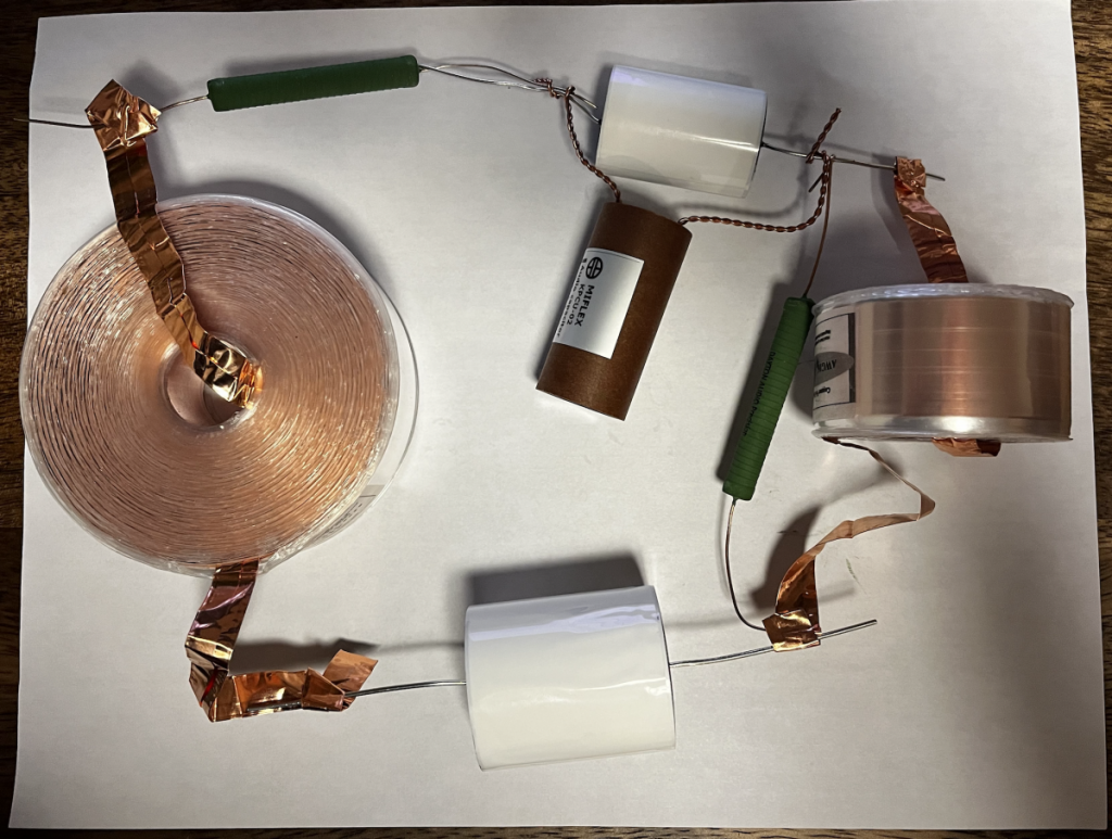
I'm beginning to work on my NX Studio crossover. I've never tried kind of project and I feel like I'm in over my head. Does this look right?

And can I run one of the foil leads on the smaller foil inductor through the hole to give me more to work with? The way it is right now, I'm looping it around the entire inductor and it uses up some of the length.


Also, I know this is DIY, but is there no instructions for this besides the Studio Monitor Crossover diagram? It'd be great to have something that tells me things like "dry fit your no-rez before you glue your cabinet together".

I know, I know... welcome to the world of DIY!

Hobbsmeerkat

  • Industry Participant
  • Posts: 2529
Re: Crossover assembly 101
« Reply #310 on: 26 Dec 2021, 02:56 pm »
Yes, that layout is correct.
No, it's not a good idea to run the foil leads through the center.

We have plans to expand the "instructions" portion of our kits to give better insight into each component and how to read the diagram and how to read the parts themselves esp resistors, many of which read like 3R3J instead of 3.3 ohm.

Theronbo

Re: Crossover assembly 101
« Reply #311 on: 26 Dec 2021, 05:57 pm »
Hobbs..

There are some PCB manufacturers…. Talk about 50 cents a board for even small(10) production runs…

Thought about it while building the AV-1RS 4x ….


That’s 1st attempt. Using longer wires so they run direct from cup to driver… the AVs are tiny enclosures anyway.

Theronbo

Re: Crossover assembly 101
« Reply #312 on: 26 Dec 2021, 07:31 pm »
4th build. Actually like this. Used long wires (tails) so you can solder directly from cup to driver. 2nd pick is test bed… wanted to verify they are working b4 putting in enclosure.


Build notes:
1. Followed schematic directly.
2. Attachment yo 3/16 pine plywood 8x4”
- ties for inductors
- hot glue for caps & resistor
- staples to hold ‘tails’ in place. Avoid stress on solder joints when handling.

Adr1an

  • Jr. Member
  • Posts: 7
Re: Crossover assembly 101
« Reply #313 on: 31 Dec 2021, 11:01 am »
My NX-Treme kit arrived, just have a question about some of the crossover components.

instead of 4x 0.1µ Sonicaps I recieved 2x 0.82µ sonicaps and 4x 0.01µ unmarked caps
Not sure where they are meant to go, I'm guessing the 0.82µ are the bypass for the mid
and the 0.01µ is the bypass for the woofers but then I have two 0.01µ left over?


Thanks in advance.

Danny Richie

Re: Crossover assembly 101
« Reply #314 on: 31 Dec 2021, 04:34 pm »
Quote
My NX-Treme kit arrived, just have a question about some of the crossover components.

instead of 4x 0.1µ Sonicaps I recieved 2x 0.82µ sonicaps and 4x 0.01µ unmarked caps
Not sure where they are meant to go, I'm guessing the 0.82µ are the bypass for the mid
and the 0.01µ is the bypass for the woofers but then I have two 0.01µ left over?

Looks like you didn't get the diagram with the latest updates on the by-pass caps.

The .82uF Sonicaps can be used in the woofer circuit.

The unmarked black caps are higher quality and more expensive Gen.3 Sonicaps and can be used as by-passes in the mid circuit.

Adr1an

  • Jr. Member
  • Posts: 7
Re: Crossover assembly 101
« Reply #315 on: 1 Jan 2022, 01:25 am »
Awesome, Thanks Danny

dasacco

  • Newbie
  • Posts: 1
Re: Crossover assembly 101
« Reply #316 on: 17 Feb 2022, 06:34 pm »
Hi, new here to the circle, I'm starting a project to build new crossovers for my Altec 604 8-G's, based on Jeff Markwart's design. I've got my parts and I'm using this great thread to gather more information on just how the heck to put these together!

Thanks! Dave

Monsoon

  • Jr. Member
  • Posts: 12
Re: Crossover assembly 101
« Reply #317 on: 27 Feb 2022, 04:12 am »
Only thing i can say is that your inductors need to be re arranged.
As they're layed out now, they'll create lots of interference with one another.

Here's a handy guide on how to best rearrange them.


Ill let everyone else speak to the rest of the issues.

right click, save as.

 8)

Simon

  • Jr. Member
  • Posts: 8
Re: Crossover assembly 101
« Reply #318 on: 8 Mar 2022, 06:12 pm »
Just came across your website and am now getting prepped to upgrade my CDMNT1. Nice to see what other folks are doing when building their networks.

joegio

  • Jr. Member
  • Posts: 5
  • here we go again
Re: Crossover assembly 101
« Reply #319 on: 17 Mar 2022, 03:10 pm »
Hi folks,

Ive always wounder about this, maybe this is the place to ask. Looking at the wire gauge for resistors, capacitors and some inductors vs the gauge of speaker wire etc and the voltage/current supply of some amps it just seems like the leads are just way to small. Obviously it works but you'd think that the leads would something like 16ga to match the rest of the wiring in the system.