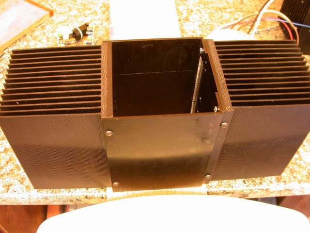
Before going on with build a few words about the heatsinks I am using. On my initial test build I was using some heatsinks rated at .4 degrees Centigrade per watt. They ran hot - so I looked around for some bigger heatsinks and found some that are normally used for mounting industrial sized diodes.
They came with mounting plates for a fan and were rated at better than .1 deg/watt in this configuration; even without the fan they are supposed to be capable of .2 to .3 deg/watt. I have not had any problems with heat using them.
Initially I was going to mount the mosfets for one channel on one of these and put the Paul Hynes regulators on a smaller heatsink as they only require 1 deg C / watt. However I decided to use the same type of heatsink for both the mosfets and the regulators and connect them with aluminium sheets so that when dealing with the expected .75 ohm load of the paralleled B200s the second heatsink could help with the additional heat.
I am hoping that this will work - I have not yet purchased the 16 required B200s.
Suffice it to say that my amplifiers run cool!
OK - on with the next part of the build.
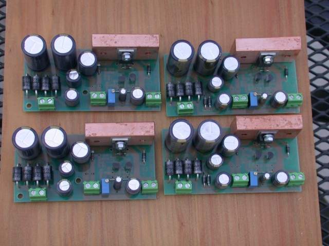
The PH regulators PR3G2-12 (12volts positive) and NR3G2-12 (12volts negative) come with a nice lump of copper to which the main regulator is clamped. So the second heatsink is drilled / tapped (3mm is fine) to take both a -ve and +ve regulator.
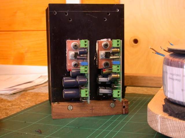
The way I had to mount them (vertically) did give me some problems in connecting them to the transformer and adjusting the regulators, I had to be careful with the screwdriver when doing the adjustment. It would make more sense to have the regulators horizontal - next time!
Plenty of goop to ensure a good heat transfer to the heatsink.
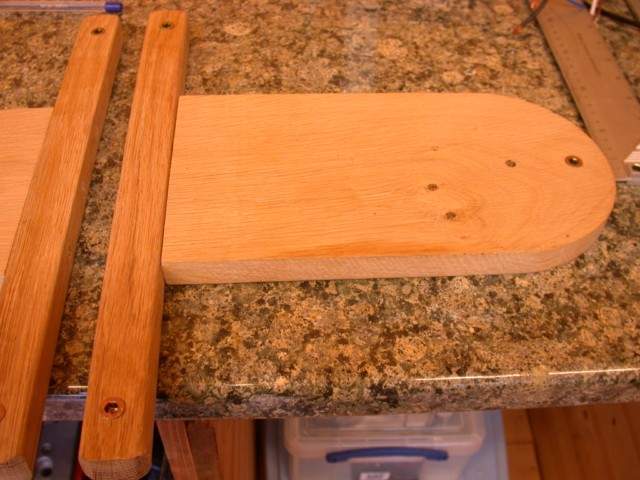
I made a base out of oak onto which the heatsinks will be mounted, to this end I attached a strip of wood to the bottom of each heatsink (drilled and tapped for 4mm bolts). Each of these strips had a pair of captive nut screwed into place so that they could be screwed into from the underside of the oak base.
The oak base was shaped to take the transformer which is mounted outside the main amplifier case. It has captive nuts into which spikes will be mounted.
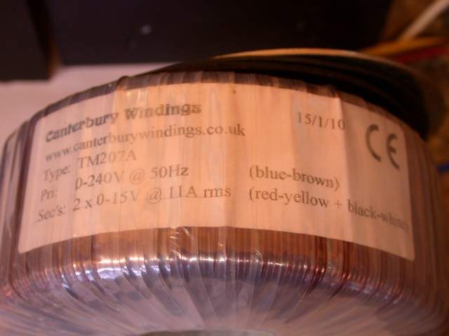
The transformer for one channel, 12-0-12 volts 330VA, a single primary 240 volts for the UK (we are supposed to be on 230V - usually it is well over 240v so if I am having a transformer made I go for a 240v primary).
The front panel has only an on off switch - there are two LEDs on the regulated power-supplies which could be wired into this panel if required. As I am going for perforated ally sheet on the top I will get a nice glow from inside the cases. The cutout at the bottom caters for the transformer wires - primary and secondaries - needless to say they are well rounded.

The rear panel has a mains inlet and should have a fuse-holder, unfortunately due to slight miscalculation it would have interfered with the regulators. So I will fit an internal fuse.

Also on the rear panel are a phono input socket and loudspeaker posts.

Next time - putting them together.


