Friends,
Thanks for asking!

I'll do the best I can to help answer your questions. For those that just can’t wait, skip to the bottom of this posting for specifications and pictures.
NuForce S-9:First of all, the S-9s can be upgraded to the new tweeter/waveguide system mentioned below. Unfortunately though, due to the modification/addition of a phase-plug to the waveguide, the enclosures will have to be returned to the factory. With regards to the improvements in performance, pretty much everything will be improved – including the bass. The S-9 will be based on the research we’ve completed in the development of the new S-8 and will take that technology to its full potential. Combining the S-9’s superior enclosure construction, high-power/high-excursion woofers and now the new waveguide/tweeter system… and we’re talking no equal in the market under $20K. Follow me below and you’ll see what I mean.
NuForce S-8:The new S-8 will truly establish a new benchmark in its price class. The first and most notable aspect suggesting this is the development of its revolutionary waveguide/tweeter system. It provides for an unprecedented, “industry first” crossover frequency of 500Hz by utilizing a new ring-radiator tweeter in combination with a proprietary phase-plug mounted centrally in the waveguide. There are numerous advantages that this offers for improved performance.
The first major advantage is reduced distortion in the midrange resulting from less Inter-Modulation distortion produced by the woofers. IM originates from the woofers as a by-product of attempting to reproduce midrange frequencies while simultaneously making the large excursions necessary to produce deep bass. The deeper and more powerful the bass being produced – the greater the IM distortion produced over the midrange frequencies being covered by the woofer. Consequently, if one reduces the range over which the woofer must operate, one will also reduce the amount of midrange IM generated.
This is generally the primary reason many speaker designs employ midrange drivers. Unfortunately, the rule “less is more” applies though, and simply adding another driver risks trading one problem (high IM) for several others. In the case of adding a midrange driver, the “down-side” is that the designer is forced to add more complexity via an additional crossover network. We all know the “evils” that crossovers can create, and I could easily elaborate on numerous aspects thereof. I will spare us all the tedium though and leave the investigation thereof up to the reader if they so choose.
Another drawback of using a midrange driver is that doing so messes up both the horizontal and particularly the vertical dispersion of the system. Instead of one main vertical dispersion “lobe,” we now have two that we need to have converge on a single vertical listening axis. The upshot is that doing so is possible, but almost invariably results in a very narrow vertical listening axis. In other words, the speaker can be made to sound good when sitting down, but not when standing… or vise-versa.
There are secondary issues that are similar on the horizontal axis, but are generally considered to be less of a concern. This is fortunate, as while horizontal dispersion is an important issue as well, there’s little the designer of such systems can do about it anyway. Oh… and this is one area of performance that a properly designed waveguide improves as well, but I digress.
The third drawback of using a midrange driver is that they suffer from the same problem that woofers do – cone “break-up” distortion. All paper, plastic, Kevlar, carbon graphite (you name it) cones, will flex and produce "bending-wave” distortion signals. Midrange drivers are just as susceptible to this distortion as any other. The only way to really avoid it is to use a diaphragm that is perfectly rigid, such as diamond. The problem with that is simply one of exorbitant cost and device “delicacy.”
The only other practical/cost efficient way is to reduce the diaphragm size, such that it is simply too small to permit these flexing waves to propagate within its given dimensions. The size required to achieve this though leads us right back to one the size of a typical tweeter diaphragm. The only way out of this quandary is to “effectively” transform the tweeter into a midrange-tweeter device by providing a means of permitting the tweeter to operate down to the same frequency as that of a typical midrange driver. The primary requirement to achieve this goal is to find a way of extending the tweeter’s low-end response while avoiding the distortion that would otherwise occur from excessive diaphragm excursion/distortion. This then represents a third advantage of this new design, and is exactly what we have accomplished with the tweeter/waveguide system employed in the S-8 (and upgraded S-9).
As evidence to the dynamic headroom/ power handling capacity of this new system, we offer the graph below. Upon inspection you will realize that the tweeter is far less stressed while being crossed over to the woofer at 500Hz, than many other more conventional tweeters crossed 2 octaves higher!
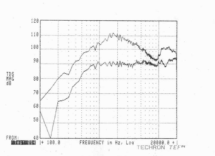
The first response curve with the big “hump” is the ring-radiator mounted in the waveguide/phase-plug assembly and measured without any crossover filters or equalization being applied. The second “flat” response curve is the same combination, but now we have applied the full High-Pass crossover/equalization network.
Please note that the SPL of this second curve is essentially the same as it would be if the tweeter were mounted on a traditional flat baffle, except for the fact that it’s response extends to –6dB at 500Hz rather than the typical –6dB at 2kHz to 3kHz crossover frequency usually used. Other than the stunning flatness of the second curve, we would draw your attention to the “difference” between it and the first curve. Specifically, notice the “area” between them. This difference represents the amount of attenuation needed to produce a flat response, and therefore the amount of drive current that is essentially being blocked from entering the tweeter. Current is directly proportional to diaphragm excursion, so excursion is reduced by the same value in decibels. As we can see, at 1.5kHz we must attenuate the drive current by -20dB, and over the entire response – from 5kHz on down - the current is reduced by no less than –10dB. It can equally be said then that any and all distortion that would otherwise arise due to diaphragm excursion (when the tweeter is mounted on a typical flat baffle), will be attenuated (when mounted in our waveguide) by the same number of decibels as that of the drive current. Considering that 10dB is a factor if x10 and 20dB a factor of x100 (logarithmic scale), this is a very significant achievement. This is all the more true when you consider that the distortion that arises in any driver is primarily that resulting from diaphragm excursion. In simplest terms, from 500Hz on up the new S-8/S-9 will offer one of the lowest distortion/highest accuracy and highest resolution performance levels of any loudspeaker in the world – bar none - and at any price point.
Finally, below we offer the complete system response graphs for your review. These graphs only span the range above 100Hz, with the phase response only accurate from 200Hz on up. Response measurements below 100Hz are complex and require special test conditions, and at this point in time our schedule has not permitted us to take them of sufficient quality for public posting.
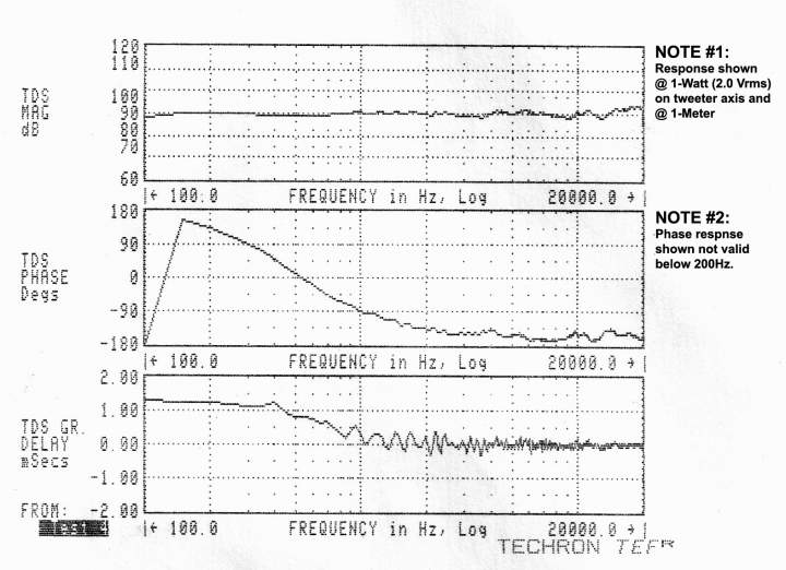
Again, other than the relatively flat response, take note of the Phase & Group-Delay Response. The G-D is less than 1.5 milliseconds and in particular, notice the response from 1kHz on up. As you can see, the Phase changes only about 45 degrees and the G-D is essentially flat. The sonic result of this is that the envelope response of a musical instrument waveform will be well preserved and highly accurate. This means that the delicate harmonic balance between fundamental notes and their harmonic overtones will be preserved and therefore be reproduced with a naturalness and realism seldom experienced. Transient response in the form of percussive instruments will be likewise, with the pluck of an acoustic guitar string as real as it gets and the snap of a snare drum rim-shot enough to make you flinch… even when you know its coming.
We could go on and talk about the imaging and sound-staging capabilities, the controlled dispersion and the elimination of diffraction artifacts resulting from waveguide technology, and more… but by now I’m sure everyone gets the point – with the point being that the new S-8 and the upgraded S-9s are VERY good loudspeakers. We're pretty certain that it won’t be long and you won’t have to take our word for it either.
Take care,

-Bob
S-8 SPECIFICATIONS:
FREQUENCY RESPONSE (anechoic)
47 Hz - 30 kHz +/- 2dB (typically +/- 1dB)
–3dB @ 42Hz & 32kHz
LOW FREQUENCY TUNNING
Proprietary Hybrid Ported Reflex
LOW FREQUENCY ATTENUATION SLOPE
24 dB/Octave below 42 Hz
PHASE RESPONSE
Less than 360° from 100 Hz - 20 kHz
GROUP DELAY RESPONSE
Less than 1.5 mS @ 100Hz
Less than 1.0mS @ 500Hz
Less than 0.5 mS @ 1kHz
0.0mS from 2kHz to 32kHz
POWER HANDLING (continuous)
120 Watts RMS
PEAK POWER HANDING
Greater than 1,000 WATTS (10mS)
SENSITIVITY
90 dB SPL @ 1-W /1-Meter
93 dB SPL @ 2.83 V
IMPEDANCE
6-Ohms (nominal)
4-Ohms (minimum)
CROSSOVER
4th-order symmetrical, in-phase
Linkwitz - Riley @ 500 Hz
MINIMUM RECOMMENDED AMPLIFIER POWER
20-Watts RMS / Channel
(150-W or more / Ch. preferred)
LOW FREQUENCY DRIVER
(2) 7” Black-Anodized Aluminum Cone w/Solid Aluminum Phase-Plug
HIGH FREQUENCY DRIVER
Waveguide Loaded 29mm Textile Ring-Radiator
DIMENSIONS
22” (55.88 cm.) H X 9.44” (23.98 cm.) W X 15.35” (39.0 cm.) D (w/Grill)
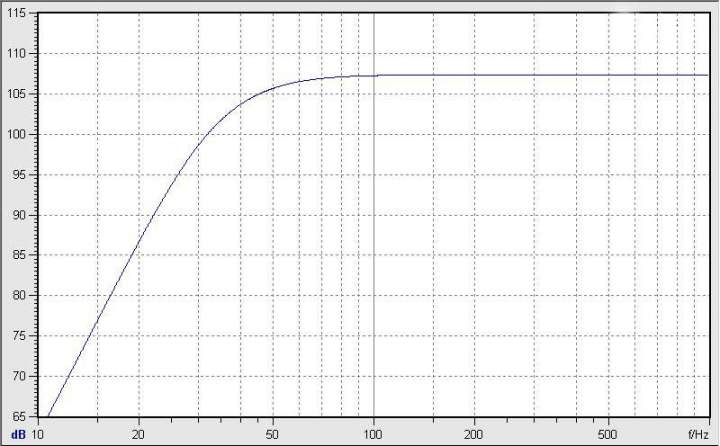
The graph below is a computer model of the S-8 low frequency response and sensitivity when being driven by the industry standard of 2.83 Vrms.
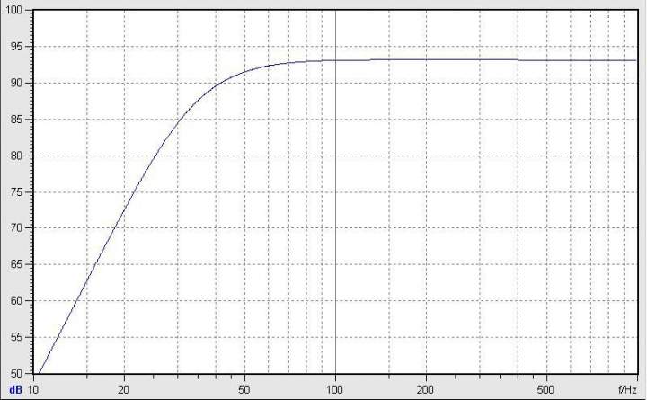
The graph below is a computer model of the S-8 low frequency response and maximum output level before reaching the woofers’ excursion limits. Add +3dB for a stereo pair.