Magnepan 1.6 Upgrade Finally Completed

0 Members and 1 Guest are viewing this topic. Read 827 times.

jspotts37215

  • Jr. Member
  • Posts: 8
Magnepan 1.6 Upgrade Finally Completed
« on: 28 Apr 2025, 03:49 pm »
I’ve had the parts on hand for this upgrade for over two years but haven’t had the time to execute it until recently. My initial thought was to go external but, after considering various options, took a more invasive approach.

The factory crossover is mounted on a small Masonite plate that attaches to the rear of the speaker. The crossover cavity is open to the front and covered by what looks like open weave black grill cloth:


With a little bit of persuasion, the old crossover and connected terminal plate can be removed more or less intact. This way, should I ever decide to sell these, a new owner has the option to undo the mods (though I can’t imagine they’d want to).


I cut a piece of 6 mm baltic birch ply 7-1/2” high x 16-3/4 wide to mount the new components, painted the front face flat black, and traced the outline of the crossover cavity on the back. There’s plenty of room on the front of the speaker to mount this panel with screws at all four corners. I laid out the components to get the maximum distance between the coils. By putting the smaller coil in the area where the old terminals connected, I got almost 8” spacing between coil centers. The control cavity is 1-1/2” deep, which is not enough to flush mount the female tube connectors and allow for a gentle bend of the 14ga input wires. I made a new plate to the same dimensions as the original out of 6 mm ply and glued on a small block of ½” MDF to raise the tube connector mounts. Keeping connector bodies out of the cavity gave me more space to accommodate the small coil.

Here's the wired crossover/input terminal prior to installation:


And here’s what the business end looks like after reattaching the grill sock and trim:


First listening impressions are snappier transients and more inner detail, e.g., when listening to vocal harmony you get the blend but can also pinpoint individual voices.

corndog71

  • Full Member
  • Posts: 1770
  • Some people call me Rob.
Re: Magnepan 1.6 Upgrade Finally Completed
« Reply #1 on: 29 Apr 2025, 12:26 am »
Nicely done!  That’s the diy way!

JCarney

  • Full Member
  • Posts: 1394
Re: Magnepan 1.6 Upgrade Finally Completed
« Reply #2 on: 29 Apr 2025, 12:49 am »
Nice work, very clean looking. You may want to consider putting one of the coils on its side to reduce interaction between the two. I supplied a chart to illustrate this. If there is room I guess I should say. My understanding number 6 is the preferred way.

JCarney


corndog71

  • Full Member
  • Posts: 1770
  • Some people call me Rob.
Re: Magnepan 1.6 Upgrade Finally Completed
« Reply #3 on: 29 Apr 2025, 01:11 am »
He said the coils are 8” apart which is just over 20cm which matches number 1.
So he’s probably fine.

jspotts37215

  • Jr. Member
  • Posts: 8
Re: Magnepan 1.6 Upgrade Finally Completed
« Reply #4 on: 29 Apr 2025, 06:44 pm »
Right. I'm familiar with that chart, which is why, when I realized I could get the recommended spacing, I decided against enlarging the cavity with a router. And though it would have been on the back of the speaker, I disliked the idea of a protruding, sideways mounted coil.

EricB

  • Jr. Member
  • Posts: 14
Re: Magnepan 1.6 Upgrade Finally Completed
« Reply #5 on: 5 May 2025, 12:34 pm »
The end result looks great. They don't look like they were modified which is nice.
Is that really four capacitors of different values paralleled together?

E-Zee

  • Industry Participant
  • Posts: 176
    • Diy speaker resources and crossover assembly services
Re: Magnepan 1.6 Upgrade Finally Completed
« Reply #6 on: 7 May 2025, 07:27 am »
JSpotts you did some excellent work with your upgrade project. Very nicely done. 

Just to add to the support for the owner's very appropriate decision to keep both coils flat, the 20cm (almost 8 inches) referenced as "okay" unfortunately doesn't quantify what "okay" is, and doesn't quantify the amount of interfering or drift in inductance that occurs by placing them closer.  The change or impact of two coils even when placed 2 or 3 inches apart is not nearly as significant as most would believe. 

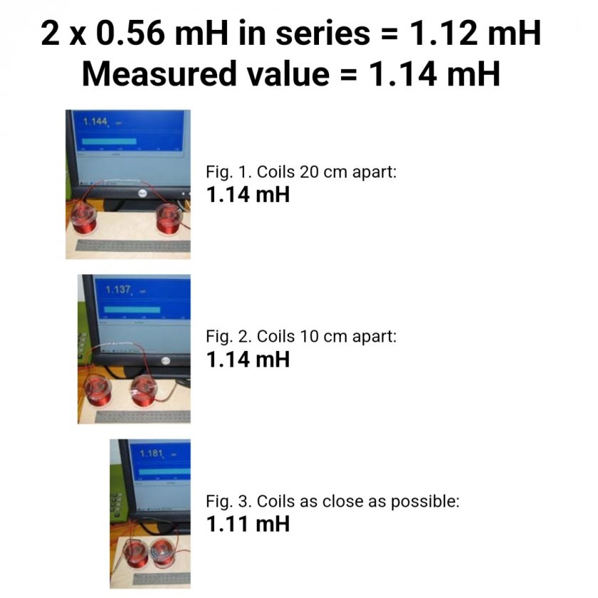
The referenced chart is a great tool to show best case practices, but the downside of the chart is an exaggeration of concerns over negative effects without any quantification, especially when some of the worst case potential harms are somewhat inconsequential. There has been plenty of testing to support this.  The photo below is from Troels Gravesen's published testing.


.
There are other factors that are relevant. Larger inductors especially in bass circuits have larger magnetic fields and can have greater impact. Coils in series receiving same signal may have greater influence on each other than coils on separate circuits and not in series (tweer coil near mid-bass coil) but bottom line is that the impact of two inductors laying flat on same plane, have only the most insignificant of impact that would not be distinguishable.

 I've tested and measured some for my own peace of mind using larger coils from bass circuit and I was not able to measure more than 3% of variance when the coils were right next to each other in that configuration. (3% would change a 1.0mH coil to 1.03mH.  Manufacturing variance from one coil to another would be greater than that). 

 Before 3" of distance, that small amount of drift was already gone.  At 7" or even 6" of distance, especially for those smaller coils, I am confident there is no effect.

Even if the space was more limited with only 2" apart and did have a 3% drift, sometimes there are compromises that must be made in a design and I would happily accept that 3% drift before going to a less desireable mounting solution.

« Last Edit: 8 May 2025, 02:07 am by E-Zee »