Bryston 2B Power Amplifier repair - updated with Distortion Measurements and Mechanical Vibration ReductionPurpose:* To share my experience repairing an early series of the Bryston 2B power amplifier.
* To verify this restoration could achieve the original manufacturer's performance specifications.
Equipment: * Bryston 2B stereo amplifier, serial number 2930.
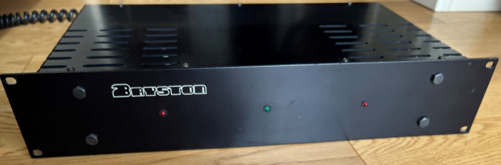
Figure 1: Bryston 2B front view after repairs -
photo taken February 2023.Background:* This 2B power-amp was manufactured 1978 which I purchased new in February 1979 from Dave Ross Stereo in Kingston, Canada. Overall, I was very pleased with the performance of this power amplifier throughout several years of worldwide assignments, faultless operation even in harsh climates.
* Although it was in full working condition, sadly I had to put my 2B into storage in 2001 due to a shortage of living space.
* Early 2022 brought my 2B out of storage and powered it up for the first time in 20 years, however the left channel was completely dead. As the 2B's components are easy to access decided to attempt repairing it.
* These repairs were successful, then later in 2025 after performing faultlessly for 3 years I had the opportunity to measure the amplifier's distortion for the first time, and as a bonus I was able to dramatically reduce the chassis' mechanical vibration noise. These results are documented in a new section at the end of this report.
Diagnosis of Left Channel: * Glass cartridge fuse 3.15A / 30 mm blown.
* Twin electrolytic capacitors Mallory 6,000 uF / 40 VDC (Fig. 2) measured
3,200 uF and
5,000 uF.
* Power transistor Motorola NPN 2N3773
Emitter-Collector measured short-circuit.
* Power transistor Motorola PNP 2N6609
Base-Emitter measured open-circuit.
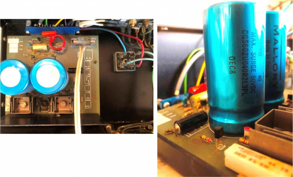
Figure 2: Original power supply capacitors, 6000 uF / 40 VDC
- cartridge fuse is on circuit board's right-hand side.Repair:* To be aware at all times of safety to equipment and yourself, when powered up both AC line voltage and +/- 37.5 VDC is present.
* The power supply capacitors I replaced with new Kemet ALS80A 103 DB 063, a plain can type that readily installs on the 2B circuit board, with added benefit of higher rating 10,000 uF / 63V, 105 Deg C.
* Please take care when ordering capacitor replacements. The Kemet ALS8
1A series have a threaded mounting stud (which is not needed), that makes for a longer overall length and may not fit within the 2B chassis - which I found out the hard way. Whereas the Kemet ALS8
0A series being a shorter length plain can type, even with a higher capacitance rating fits nicely within the dimensions of the 2B chassis (Fig. 3).
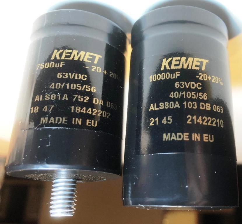
Figure 3: ALS81A 7500uF with threaded mounting stud
(left), best fit ALS80A 10000uF plain can type
(right).* The three smaller electrolytic and two tantalum capacitors on each circuit board were tested and all within specification and functional, but as a precaution replaced them with higher grade new.
* Left channel power transistor 2N3773 replaced with higher rated MJ15024. Power transistor 2N6609 replaced with higher rated MJ15025. Renewed the TO-3 size mica insulators and silicon insulating grease.
* Replaced glass cartridge fuse with a standard 3A / 30 mm type.
* The original 10K bias potentiometer was an open-face type (Fig. 2) and although still working had captured some dust over the years, as precaution replaced with closed type potentiometer of same rating 10K (Fig 4).
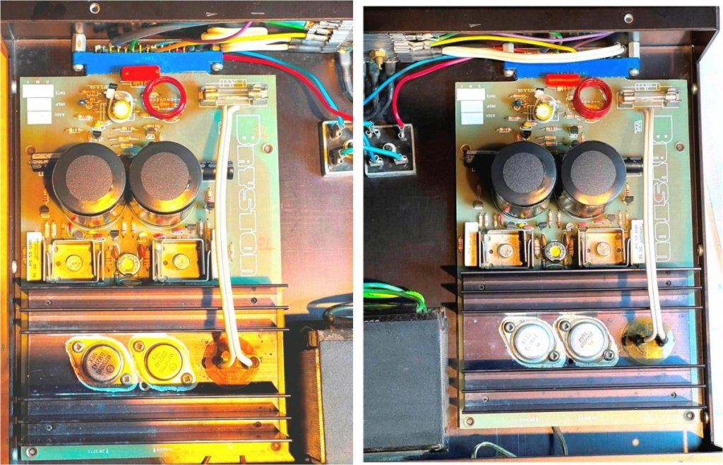
Figure 4: Left and right channel boards with closed type bias potentiometers installed
- Year 2022.* Except for the power transistors, all component replacements were repeated for the right channel.
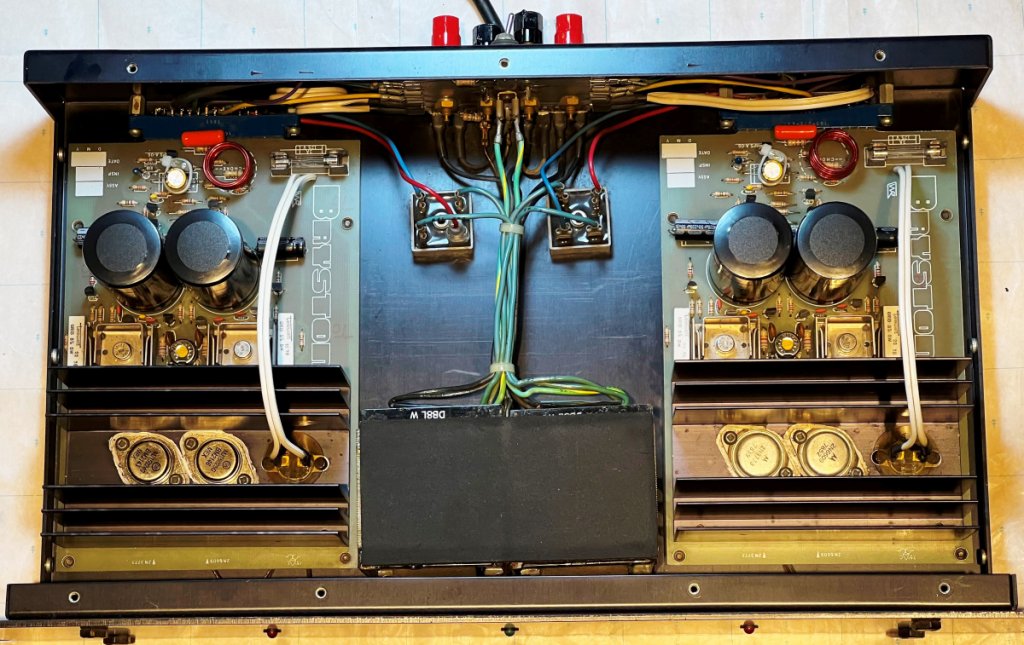
Figure 5: Internal view after repairs completed - new MJ15024/MJ15025 power transistors on left channel heatsink
- Year 2022.Measurements after repairs - Year 2022:* Whenever replacing the bias potentiometer and/or the power transistors it requires a resetting of the bias current. The instructions for setting the bias level are well documented in Bryston's 2B Technical Data sheet "Burn-in Procedure".
* Ensure the AC supply voltage is stable before performing this measurement.
* With the amplifier fully warmed up after a few hours operating, I set both channel's bias values to between 9 ~ 10 mV, measured between the V+ red terminal of the bridge rectifier and the 100-ohm resistor. This setting proved to be the most stable, even when driven at the highest output power level.
* Hint, patience is required for the bias adjustment. While changing the bias potentiometer setting induces an immediate electrical change, with thermal lag it may take a few minutes for the temperature feedback sensing to fully respond. Suggest when changing the bias current setting, to do it a small step at a time, then wait for the system to stabilize and re-check the measurement. When I first set the bias, I didn't pay attention to this and as a result the amplifier became very hot after a few hours of playing music.
* As a general guideline, if you place your hand on the 2B's top panel after a few hours of playing music and it's warm to the touch, the bias current is likely okay. But if the surface is hot to the touch and/or the power supply is overloaded causing the chassis to hum then the bias current is likely running too high.
* Last check, with the analog inputs shorted to ground, the DC offset measured across the output terminals was +4mV left channel and -6 mV right channel (single digit mV values are considered excellent).
Update 2025:
* After performing faultlessly for 3 years, I had the opportunity to measure the amplifier's distortion for the first time, and as a bonus I was able to dramatically reduce the chassis' mechanical vibration noise.
Distortion measurements:* To investigate the effect of output stage bias level on crossover distortion, a challenge was to obtain stable bias readings with the single turn potentiometers, just a 1/4 of a turn could change the quiescent current from fully off to fully on. These single turn potentiometers were changed to CT9W-10k multiturn potentiometers, and while the leads must be carefully bent to fit, the multiturn potentiometers fit nicely on the PC board (Fig. 6).
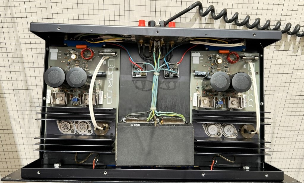
Figure 6: Internal view showing the new blue-coloured multiturn potentiometers installed
- Year 2025.* Using my recently purchased QA403 Audio Analyzer, the amplifier's performance was measured using the setup shown in Figures 7 and 8. The QA403 has differential inputs and outputs and can be susceptible to external noise from cables. Constructing a pseudo-balanced cable configuration, while not perfect, provided better noise immunity with the Bryston 2B's single-ended inputs.
1) QA403 outputs connected to the 2B amplifier single-ended inputs with coax cables.
2) QA403 inputs connected to the 2B amplifier output binding posts with shielded twisted-pair cables. Note shields connected only at the QA403 BNC inputs.
3) Offset voltage: Measured at the output binding posts, power on for 2 hours, inputs shorted.
4) Bias voltage: Measured between V+ Red terminal of the bridge rectifier and 100-ohm resistor. Power on for 2 hours with cover in place, inputs shorted. To minimize temperature changes the cover needs to be kept in place throughout this measurement, suggest running small test leads to an outside DVM.
5) RMS Power: Both channels driven, QA403 Audio Analyzer providing 1 kHz input signal with amplifier output measured at binding posts upstream of 8-ohm load.
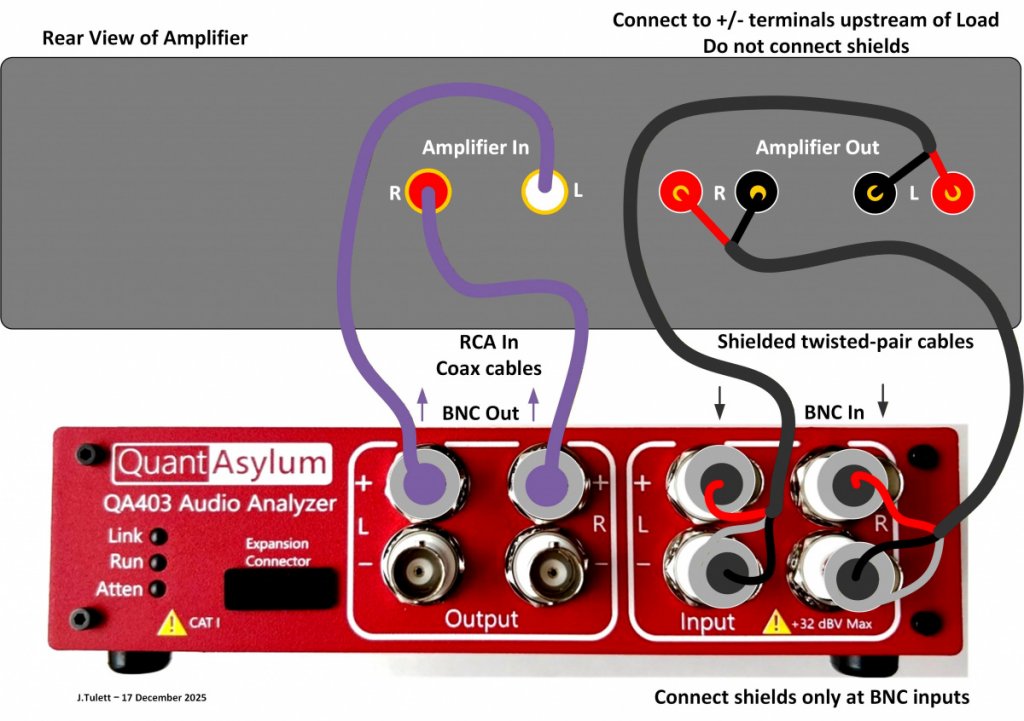
Figure 7. QA403 Audio Analyzer connections to amplifier under test
- single-ended coax cabling with shielded twisted-pair cabling.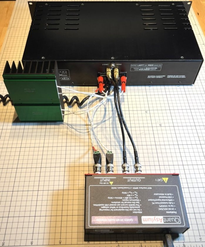
Figure 8. QA403 Audio Analyzer connections to Bryston 2B amplifier with twin Arcol 8-ohm, 100W heatsinked resistor loads.
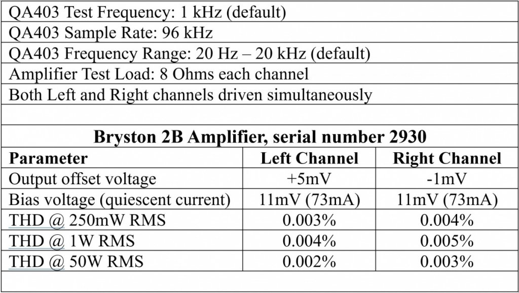
Table 1. Measured amplifier performance
- Offset voltage, Bias voltage, and Total Harmonic Distortion.* Using the same pair of Arcol 8-ohm, 100W heatsinked resistor loads, another test was to verify the amplifier could indeed deliver clean, full 50W RMS power into both channels (Fig. 9).
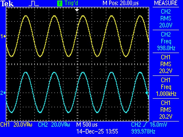
Figure 9. Power output driving a pair of 8-ohm resistor loads
- 20V RMS corresponds to 50W RMS.
* Yet another test was to slowly increase the signal level to observe when clipping appeared on the oscilloscope screen, this happened around 22V RMS (not shown).
* An attempt was made to investigate how the bias voltage impacted the Total Harmonic Distortion (THD) measurements. Following the Bryston 2B burn-in procedure the bias voltage was initially set between 6 and 8mV, however the THD results from this initial bias setting were only slightly less favourable than those obtained with the final 11mV bias setting in Table 1. Next, apart from an increase in heat generation and power consumption, advancing the bias voltage past the upper recommendation of 12mV did not reveal much reduction in THD. From this simple investigation, Bryston's recommended 10 to 12mV bias setting for this amplifier is appropriate.
* Considering this amplifier is 47 years old I was very pleased with these results, both left and right channel THD measurements are excellent, achieving the original manufacturer's specifications.
* Why is the left channel THD slightly better than the right channel THD I'm not sure (Table 1), possibly it's the newer power transistors installed on the left channel, or perhaps it's my home-made interconnect cables influencing the measurements.
Mechanical Vibration Reduction:* With the amplifier on the workbench, I took this opportunity to investigate the cause of mechanical vibration hum. To be clear this is not loudspeaker hum, rather it's a mechanical hum emanating from the twin power transformers. This is an issue that only appeared after decades of use, it was not like this when the amplifier was new.
* What I observed was installing the fastening screws on the side panels induced the hum, while removing the fastening screws from the side panels reduced the hum - how strange is that?
* Noting that the front 19-inch panel was vibrating, then tracing the path of this vibration along the front panel, I found this vibration was coupling into the side panels when the side screws were tightened.
* Removing the front 19-inch panel (requires 7/16-inch spanner and nut-driver) exposed the culprits, a set of tape and felt strips that had deteriorated/compressed over the years (Fig. 10). These were replaced with fresh strips cut from vibration damping sheet INOAC Calm Flex material RZ which I had on hand, although other vibration damping materials should also work.
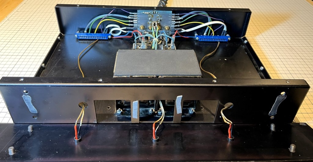
Figure 10. Front panel opened exposing the original tape strips and felt strips.
* A word of caution with this work. When reinstalling the front panel, it broke the middle Green LED, which I initially thought was due to my carelessness, however one by one the other two Red LEDs broke in the same manner (Fig. 11). Presume the protruding leads had weakened with age, all three LEDs were replaced with standard 5mm diameter LEDs, together with fresh red/black heat shrink tubing (Fig. 10).
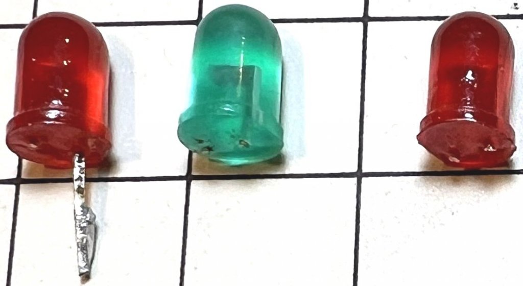
Figure 11. Original front panel LEDs, leads broken in the same place
- each square represents 1cm.* With everything put back together the reduction in vibration noise was remarkable. Of course, it's not dead silent and would not expect it to be with an amplifier manufactured before toroidal transformers became commonplace, but it's now as I remember when it was new.
Final notes:* The reason for this writing is to share my experience repairing a Bryston 2B power amplifier. It's not an endorsement of any component supplier or to bypass factory repairs, just to share what worked for me. At time of this writing the board repairs have been operating without issue for 3 years now.
* And finally, pleased to report my repaired 2B is fully operational and sounds great just like it used to!


