Thanks -this is a Topaz unit
I was told to wire it this way -
> So the side that you attach to the wall voltage is the "H" side. The output side should be is the "X" side.
>
> Incoming:
> Hot wire connect to "H1"
> Common wire connect to "H3" (assuming your wall power is 120V, which it should be)
> Ground connect to "Chassis"
> On this model I am not 100% sure the best way to attach the shield (S1). You could try it either connected to "Chassis" or to "H1", as I have seen both used on other Topaz (the units with 120/240 set ups) but I am not sure on this dedicated voltage unit how best to do it. You can try playing with it and see what works for you.
>
> Outgoing:
> Hot wire connect to "X1"
> Common wire connect to "X2"
> Ground connect to "Chassis"
> Same advice on the shield S2 as from S1 above.
> I usually mount a 3 plug dual wall outlet on the output side.
I forget what I did with the Shield (S1 and S2) as I wired this up with instructions from a e-audio buddy in early 2012
I could take it apart and check/experiment but it's much quieter right now
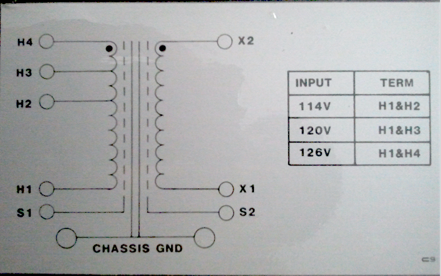
Here is the wiring diagram
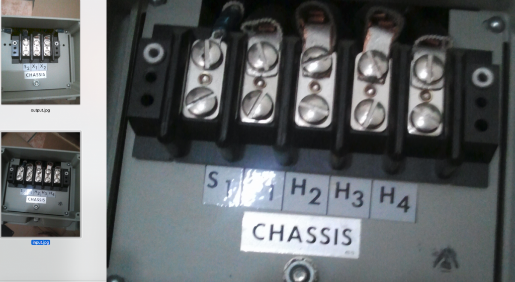
and input and output physical connections
Because you are using a cord and plug, to feed the transformer that is plugged into a 120V wall receptacle.
The Hot wire of the cord should connect to H1.
The neutral wire from the cord to H3
The safety equipment grounding conductor, wire, from the cord connects to the metal chassis/enclosure, of the transformer. ALL other grounds will connect to this point.
* Both S1 and S2 connect to the equipment ground chassis ground point.
Secondary winding.
* X2 needs to be connected to the equipment chassis ground point. This makes X2 winding lead the neutral conductor. (The grounded Conductor) This will also connect to the silver color screw on the output duplex receptacle.
* X1 becomes the HOT (The ungrounded Conductor) and connects to the copper/brass color screw on the receptacle.
* The green color safety equipment ground screw of the receptacle connects to the equipment ground chassis ground point.
//
Test for proper AC polarity.
Measure for voltage from the Hot contact of the output duplex receptacle to the neutral contact. You should measure 120Vac, nominal.
Measure from the Hot contact to the safety equipment ground "U" shaped ground contact. You should measure 120Vac, nominal.
Measure from the Neutral contact to the "U" shaped ground terminal. You should measure zero volts.
In the world of your new separately derived Grounded AC power source/system the equipment ground chassis ground point is the system ground for the ISO transformer.
* Next test.
Because you are using AC power from your main electrical service to power other audio equipment in your system, that is connected to the power amps by wire ICs you want both 120V power systems to be in phase with one another.
Measure for voltage from the Hot contact of the transformer's output duplex receptacle to the Hot contact of the wall duplex receptacle that the other audio equipment plugs into.
If the 120Vac output of the transformer is in phase with the mains 120Vac power feeding the wall receptacle you should measure zero volts, nominal.
IF the two 120Vac power sources are out of phase with with one another you will measure 240Vac, nominal.
If out of phase post back and I will tell you what you need to do to so both will be in phase with one another.
Are both wall receptacles that feed the transformer and the other audio equipment fed from the same Line, leg?
I will need to know if both branch circuits, feeding the wall duplex receptacles feeding the transformer, and the one feeding the other audio equipment, are fed from the same same Line, leg, from the main electrical service electrical panel. You can easily find out by measuring for voltage from one hot contact of one duplex receptacle to the hot contact of the other duplex receptacle. If both are fed from the same Line you will measure zero volts, nominal. If one is fed from one Line and the other from the other Line you will measure 240Vac nominal.
.
.


