Purpose* The purpose of this report is to document the investigation of poor Wow and Flutter (W&F) results, the corrective actions taken to improve the W&F, and to share these findings with our members.
History* This B710 MK1 serial number 003055 I purchased new in February 1982 and used it successfully in several countries worldwide, until it had a failure circa 1990-1991 requiring it to be sent to Studer ReVox in 1992 for repairs. While undergoing service by Studer ReVox, all applicable factory upgrades were implemented, bringing it closer to MK2 status (Appendix, Table 3 and Fig. 22).
* Since the 1992 repair and upgrades my B710 performed without issue, but in 2000 it had to be put in storage due to limited living space.
* Bringing it out of storage in 2022 I began a major restoration, and while I had experience successfully restoring my B790 Turntable and B739 FM Tuner/Preamp, I had no experience restoring a tape deck of any kind and hence proceeded with extreme caution.
Restoration* To start, as the original Nextel finish was faded and in places had peeled, the external panels were repainted with a matching colour industrial paint (Fig. 1).
* An excellent kit of the important replacement parts and maintenance supplies was purchased from Nagravox, Australia.
* After installation/updating of the components in the kit and reassembling the unit, was pleased to observe the unit powered up first time, all functions operable.
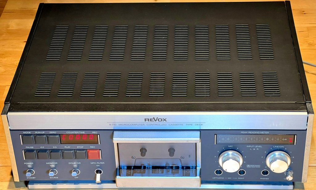 Figure 1. Front view of restored B710 MK1 Cassette Tape Deck - photo taken January 2023
* Although all functions worked correctly, the W&F results were considerably outside of Studer ReVox's specifications.
Investigation* Significant progress was achieved with the following.
a) Pinch roller size compatibility
b) Pinch roller force setting
c) Solenoid plunger adjustment
d) Capstan motor servicing/lubrication
e) Capstan thrust bearing POM improvement
f) Counter torque / back tension setting
g) Wind motor reliability
h) Head azimuth alignment
* For the W&F measurements, I used my existing AnalogMagik turntable/cartridge test program, which was invaluable in setting up my vintage ReVox B790 and Oracle Premiere turntables, then feeding this test program with a wow and flutter master calibration tape ordered from GennLab, New Zealand having recorded parameters 3.15kHz, speed 1-7/8 ips.
* While a bit unusual, this combination performed well for the purpose of this investigation, and already being familiar with the AnalogMagik program and its setup, my additional cost was just the calibration tape. Some examples where I gained experience with the AnalogMagik test program for W&F measurements.
a) ReVox B790 Turntable - Motor Servicing Hints & Lessons Learned.
(W&F shown in Figure 11). https://audiokarma.org/forums/index.php?threads/revox-b790-turntable-motor-servicing-hints-lessons-learned.1025344/ b) Oracle Premiere Turntable: A Successful Restoration.
(W&F shown in Figure 7). https://www.audiocircle.com/index.php?topic=186862.0* The AnalogMagik turntable/cartridge test program follows the Audio Engineering Society (AES) standard using a Weighted Peak Flutter measurement.
* Quoting from the GennLab website, "
The residual W&F of the tape itself is 0.022 % RMS WEIGHTED measured to NAB / JIB C5551 Standards using for playback the same MX5050 Reel to Reel tape recorder the tape has been recorded on. A few measurements of the same tape portion have been done using a Neutrik A2 analizer. The results from 0.008% to 0.036% averaged to 0.022%." Following this statement, the actual W&F of the unit may be slightly lower than the values presented in this report.
* An interesting feedback after posting this initial report was a request to repeat the W&F measurements in recording mode, that is to record a 3150 Hz tone to blank tape and then use this self-made test tape for a check of the overall W&F in playback. This supplementary test is presented at the end of this report, reference Figures 16 to 21 and Table 2.
Pinch Roller Size Compatibility* Based on my B710 MK1 early status serial number 003055, it was factory fitted with 8.7mm pinch rollers on both left and right sides, and this matched the size of new pinch rollers supplied with the Nagravox restoration kit.
* Overlooked at the time of kit ordering, my B710 had been repaired by Studer ReVox back in 1992, where the erase head was changed to new type necessitating a smaller size 8.0mm left pinch roller (right side pinch roller remained the same size at 8.7mm and installed without issue).
* Reporting this finding back to Nagravox, I was kindly supplied free of charge a new replacement smaller size left pinch roller which I installed without issue - I thought that was very good service.
Pinch Roller Force Setting* To adjust the pinch roller force, I purchased a pull-tension gauge made by Nakamura Mfg., model KANON TK500CN (Fig. 2), where the number 500 indicates a maximum reading of 500 centi-newtons (5N). This is a good match for measuring the left-hand and right-hand recommend pinch roller force of 300cN (3.0N) and 480cN (4.8N), respectively. For horizontal measurements, the tension gauge is supplied with a compensation chart. With model TK500CN, 30cN must be added to the measured value when the tension gauge is deployed horizontally.
* Next, I purchased a set of 12mm length nylon spacers having M3 internal threads, then drilled a thru-hole to fit a pull wire (Fig. 2). M3 is the thread size of the two pinch roller adjustment set screws and these mated perfectly with the threaded nylon spacer. A small loop was made in the pull wire to attach it to the tension gauge's hook.
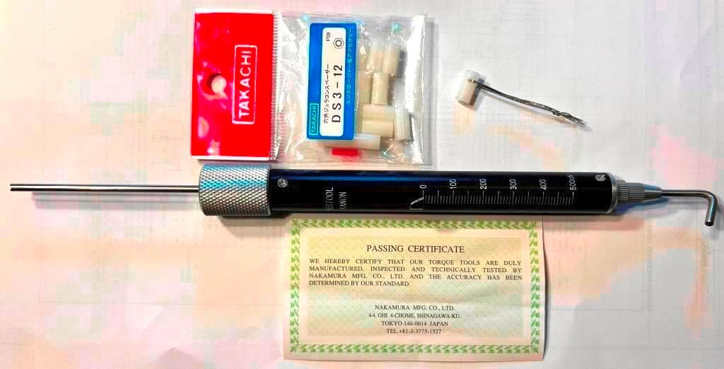 Figure 2. Tension Gauge model KANON TK500CN (Left)
,
M3 nylon spacer with looped pull wire (Right). * Pressing the front panel
Red "CLEAR" button to engage the pivoting carrier, then gently pulling on the tension gauge until the square adjustment nut just lifts, the corresponding pull tension can be seen (Fig. 3).
 Figure 3. Setting the right-hand Pinch Roller tension to the recommended 480cN (450cN + 30cN horizontal correction factor)
* Per the B710 service manual, the left-hand and right-hand pinch roller force was set to the recommended 300cN (3.0N) and 480cN (4.8N), respectively.
* Later, I experimented with some different pinch roller forces to observe if it impacted the W&F results.
* On spooling motor control PCB 1.710.463, potentiometer R5 and voltage drop across resistor R27 remained at the recommended value (200 mV) as set by Studer ReVox.
Initial W&F result* While adjustment of each pinch roller force is straightforward by turning its square nut accordingly, no matter what each pinch roller force was set to the wow & flutter was terrible (Fig. 4), to the point that when the unit had warmed up playback was unlistenable.
* Obviously, this was not a useable situation and so next step was to service the capstan motors.
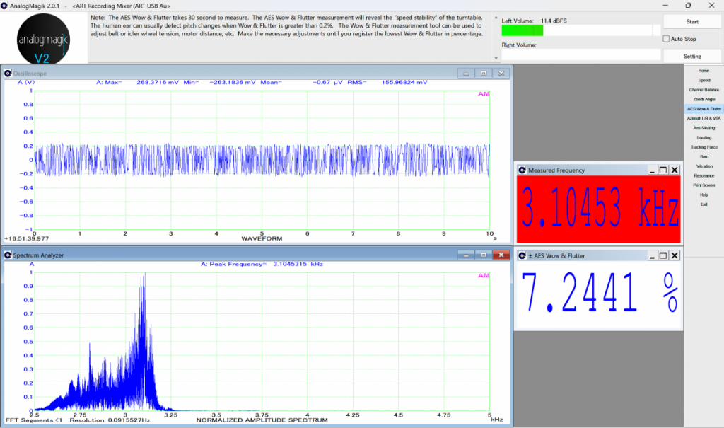 Figure 4. Initial example of an AES poor W&F after warmup - not good. Capstan Motor Service
* It's a delicate task to remove the tape drive chassis and perform this servicing, extreme care is required.
* To preserve factory W&F settings, the original positions of the shaft lock clips were marked on each flywheel (Fig. 5).
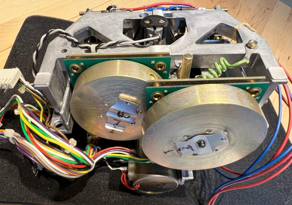 Figure 5. Flywheel shaft lock clips marked with original factory positions
 -
tape drive chassis resting on soft foam sheet.* Each capstan shaft was carefully removed, cleaned and lubricated with fresh PDP65.
* Likewise, the sintered bearings were carefully cleaned and lubricated with fresh PDP65.
* After reassembly paying attention to the correct order and orientation of all parts, there was an improvement in W&F measurements (Fig. 6).
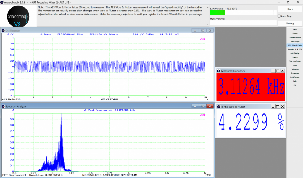 Figure 6. Following example of an AES poor W&F after capstan motor service - still not good.Solenoid Plunger Adjustment
* Feeling despair at this stage, I consulted the Studer ReVox service manual, section
5.5.5 Wow and flutter where it states,
"If these wow and flutter figures cannot be achieved it is recommended to readjust the plunger solenoid as per 3.4.5.", which I proceeded to do.
* Section
3.4.5 Adjusting the pinch solenoid and the dashpot instructs to first
"tighten the plunger's nut with two 7mm open end wrenches until the disc spring is fully tensioned." However, with a +40-year unit the plunger nut was frozen stiff, and I ended up shearing the threaded shaft (Fig. 7). Yeah, I know, brilliant.
 Figure 7. Solenoid Plunger, threaded shaft sheared
* Finally, after some months I could receive a used solenoid plunger, installed and adjusted it to the correct position as described in service manual section 3.4.5.
* With the unit now operational, repeated the W&F measurements and was pleasantly surprised to see an improvement in W&F, approx. 0.47% after playing for 30-minutes (Fig. 8).
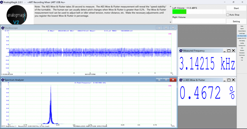 Figure 8. Example of an AES improved W&F after setting the solenoid plunger position.
* Why did the W&F results improve? Setting the solenoid plunger to the correct position helped, another possibility could be after sitting for some months it allowed the freshly applied PDP65 lubricant to seep throughout the sintered bearings. Although I have no way to quantify the effectiveness of these changes, quoting Studer Technical Protocol No. 174 provides some useful information.
"Lubrication of sintered Bearings in Capstan Motors. The pores in the bearing material are amounting to 15 - 30 % of the bearing's volume... After about 60 to 70 % of the originally absorbed lubricant has been lost, the sintered bearing will no longer perform satisfactorily. This may become evident in a degraded wow and flutter performance or in that nominal speed can no longer be reached..." Adjusting the Counter Torque* As mentioned, on spooling motor control PCB 1.710.463, potentiometer R5 and the voltage drop across resistor R27 remained as set by Studer ReVox at the recommended value 200 mV. Thinking the counter torque might be loading down the capstan motors, I experimented with adjusting R5 to vary the voltage drop across R27.
a. R27 set at standard 200 mV. As above, initial W&F ~0.47%.
b. Decreased R27 voltage to 145 mV, W&F improved to ~0.30%.
c. Same R27 voltage 145 mV, after 30-minutes play W&F deteriorated to ~0.40%.
d. Returned R27 voltage back to 200 mV, after 30-minutes play W&F at ~0.5%.
e. Decreased R27 voltage to 130 mV, after 30-minutes play W&F above 0.5%.
f. Returned R27 voltage back to 200 mV, after 30-minutes play W&F above 0.5%.
* And so on. No matter the value of R27 voltage setting, once W&F increased the W&F continued to remain high.
* From these results, whatever the amount of counter torque (back tension) was, it was not a major contributor to the poor W&F.
New POM Thrust Bearings* After receiving new low friction POM thrust bearings, the tape drive chassis was again carefully disassembled and the capstan motor service performed, replacing the original thrust bearings (1.021.510.14, Fig. 9) with new POM type (1.021.520.20).
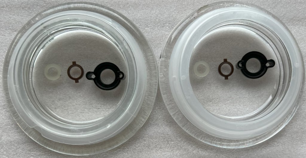 Figure 9. Original capstan bearing parts replaced - from L to R; Front Sealing Washer, Thrust Bearing, Flange
* After changing to the new POM thrust bearings and performing the service again with fresh PDP65 lubricant it resulted in the W&F being further reduced (Fig. 10).
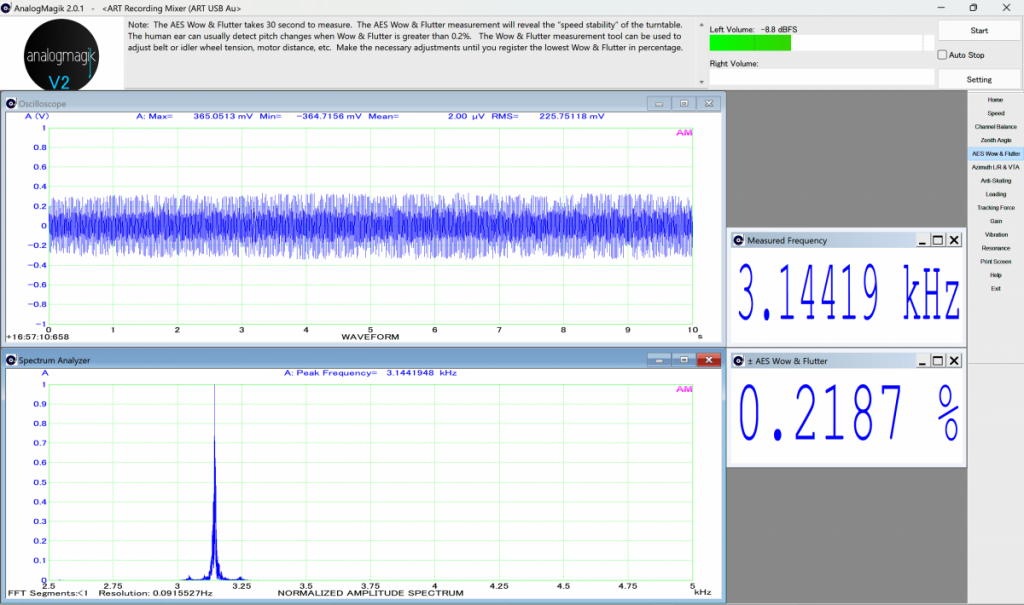 Figure 10. Example of an AES W&F after servicing and installation of new POM bearings.
* Although the instructions clearly state this is not required, I placed one drop of PDP65 on each of the pinch roller shafts and was surprised this gave a further improvement (Fig. 11).
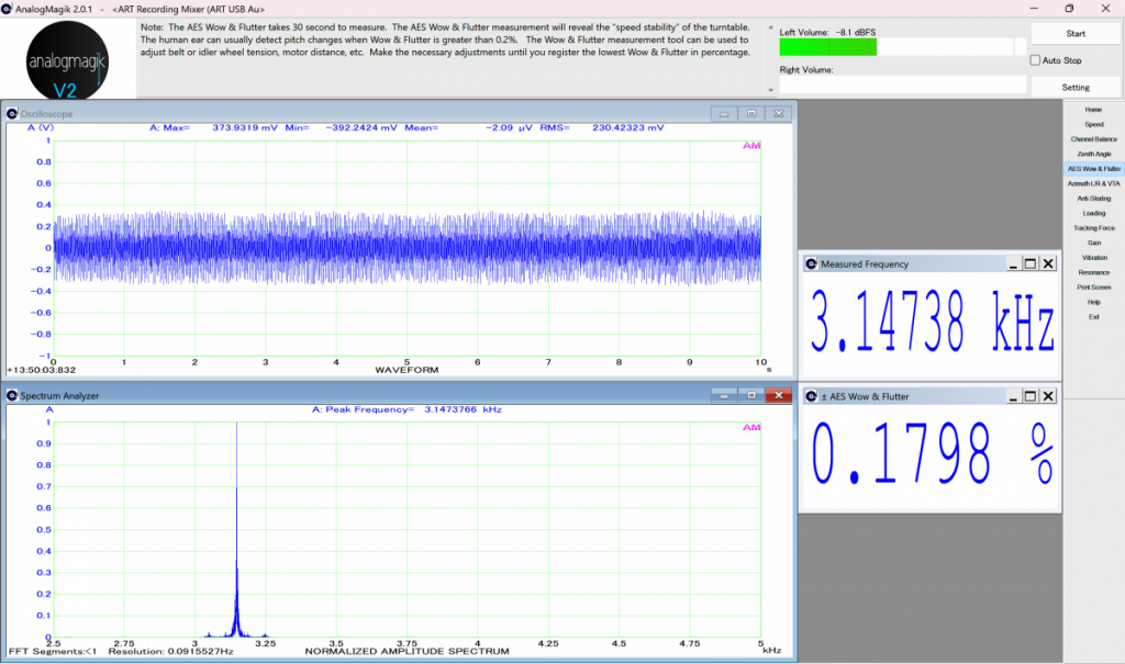 Figure 11. Example of an AES W&F after one drop of PDP65 applied to each pinch roller shaft.
* In hindsight, it would have been more instructive to sequentially put the drop of PDP65 on each pinch roller shaft one step at a time, to learn when lubricating each pinch roller bearing which one made a difference.
* But as the W&F figures started to stabilize (albeit still high) this was a significant improvement. After conducting hundreds of these tests, a pattern started to emerge.
* At startup with the system cold the W&F results had reduced to around 0.14%, but when rotational loading on the transport mechanism caused the W&F to increase and exceed say 0.2%, the electronics and/or motors heated up reducing their efficiency, leading to further heat buildup. In such situation, no matter what adjustments were tried the W&F remained high, with the only way to recover the W&F was to switch power off and let the unit cool down and start again.
* On the other hand, if loading on the transport mechanism kept the W&F below say 0.15%, the electronics and/or motor efficiency was still capable of maintaining this level of W&F so the system remained stable.
* In other words, if W&F went above 0.2% the system was unstable, but if W&F remained below 0.15% then stability could be maintained. It may sound crazy, but with so many W&F tests conducted this trend was repeatable. It also helped explain my frustration with the earlier measurements, with such high W&F figures the system was overheating and unstable and, in that situation, other than powering down nothing could be done to rectify it.
Adjusting Pinch Roller Force and Counter Torque settings* With the new POM thrust bearings installed, servicing and PDP65 lubrication of the tape transport mechanism and pinch roller shafts, the W&F, although still out of specification, had significantly decreased in value and became more stable. With these more favourable conditions it allowed some experimenting with adjusting the pinch roller force and counter torque (back tension) settings.
* All previous examples were measured with recommended left pinch roller force of 300cN, right pinch roller force of 480cN, and for back tension recommended R27 voltage drop of 200 mV. By reducing these values, I believe it influenced a reduction in the transport mechanism's rotational loading.
* Encouraging W&F results (Fig. 12) were obtained by reducing the left pinch roller force down to 245cN, together with setting R27 voltage drop to 130 mV. For comparison, decreasing the right pinch roller force to 460cN or increasing it to 500cN had only a minor effect.
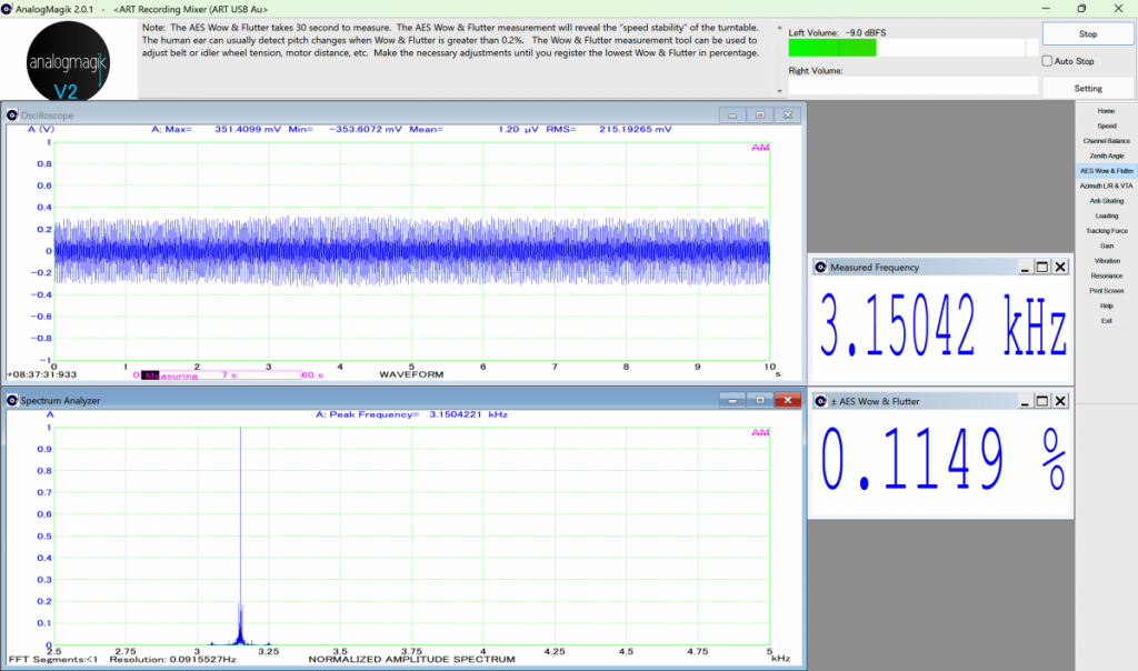 Figure 12. Example of an AES W&F with Left pinch roller 245cN, Right pinch roller 480cN, and R27 130 mV.
* While these W&F results are certainly encouraging, unfortunately by reducing the left pinch roller force and reducing the counter torque / back tension the tape handling was compromised causing older tapes to be mangled - not nice.
* Clearly this was an unsatisfactory situation, prompting me to return to the manufacturer's recommendations of Left pinch roller force 300cN and R27 voltage drop of 200 mV.
Wind Mode Reliability* Although music tapes could now be listened to and enjoyed, with certain older tapes the W&F was noticeably poor in sections. At first, I thought this was caused by the B710 tape transport mechanism, but the cause was within the tape cassette itself. With aging cassettes, internal friction and stiction had increased over the years. Also, these poor tapes would randomly halt during fast forward or rewind operations.
* Fortunately, there was a remedy for this, described on page 12 in the Studer Service Instructions SI 106/87.
a)
On the component side of microprocessor board, solder two 1N4001 diodes in series with D2 and D3. This diode modification was already implemented by Studer ReVox during the repair in 1992.
b)
If no essential improvement after a) is done, solder on the back side of the back tension PCB two 1.2 kOhm resistors in parallel. Although deemed not necessary by Studer ReVox back in 1992, I implemented this modification in 2024 as part of the restoration (Fig. 13).
 Figure 13. Twin 1.2 kOhm resistors soldered to back side of back tension PCB - installed July 2024.
* This proved to be an effective modification. After repeated fast forwarding and rewinding motions, even poor cassettes could now play music with no further degradation in audible W&F.
* Side note, implementing this modification changed the R27 voltage drop, necessitating an adjustment of potentiometer R5 to restore the back tension.
Final Capstan Motor Service * All settings were returned to manufacturer recommendations, these are the final values retained for this restoration.
* Left pinch roller force, final value: 300cN (270cN measured + 30cN horizontal correction factor).
* Right pinch roller force, final value: 480cN (450cN measured + 30cN horizontal correction factor).
* R27 voltage drop (back tension), final value: 195 mV after warmup.
* With all settings restored to manufacturer recommendations, I decided to overhaul the tape drive chassis once more (my third attempt!), paying careful attention to details like; axial end play of shafts, component clearances, effective application of PDP65 lubricant etc.
* A summary of my investigations and findings is listed in Table 1., all these efforts played a part in bringing the W&F measurements to within manufacturer specifications. The pinch roller condition and proper lubrication was observed to have the biggest impact, but even the "Minor Improvements", while on their own only contributed a small amount, when taken together these improvements were also substantial.
* Please note this is not a comprehensive list, there could be other factors that affect W&F, this is only to share my experiences and what worked for me.
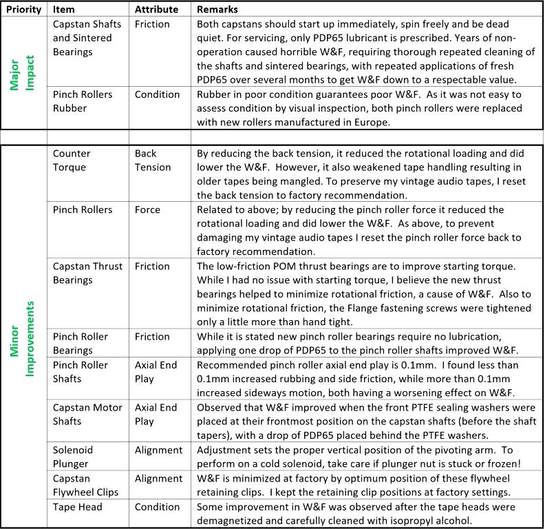 Table 1. Summary of W&F investigations and improvements.
* Lastly, the reproduce head azimuth was optimized using another GennLab calibration tape for this purpose. With pre-amp switched to Mono mode to combine both channels, using a non-magnetic screwdriver the reproduce head adjustment screw was rotated for maximum amplitude on the oscilloscope traces (Fig. 14). In this case, the adjustment screw was turned approx. 30 Deg. CCW.
* Minimum phase between the two channels was then confirmed on the oscilloscope traces by switching the pre-amp back to stereo mode (not shown).
* While the azimuth optimization did not appear to affect the W&F, it made a remarkable improvement in the audible high frequencies when listening to music.
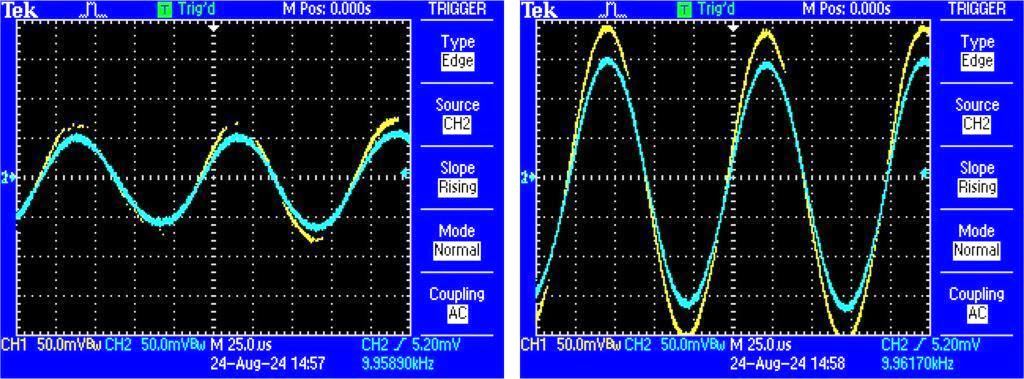 Figure 14. Reproduce Head Azimuth adjustment, 10 kHz calibration tape, Mono mode. Before (left), Amplitude optimized (right).
* Final W&F measurements were made with the pinch roller force and back tension at manufacturer recommendations, the final capstan motor service performed, and reproduce head azimuth alignment performed. Figure 15 shows a typical example, compared to the initial measurement (Fig. 4), this represents roughly two orders of magnitude improvement in the W&F measurement. There is also a small boost in signal amplitude, presume coming from the azimuth optimization.
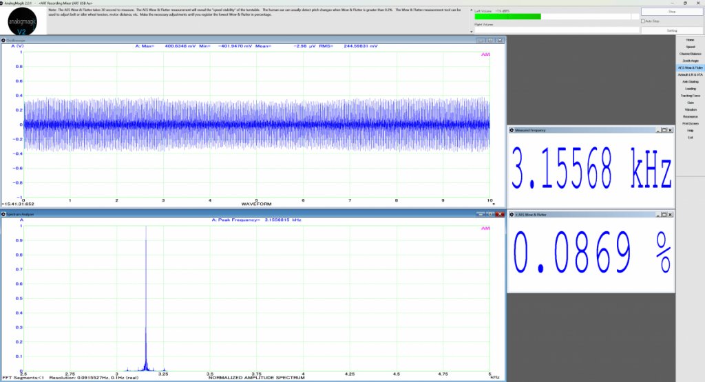 Figure 15. Example of an AES final W&F measurement.
* To simulate typical operating conditions, I made forty (40) W&F measurements with the unit first warming up, then fully warmed up, various positions along the calibration tape, different times of day etc. From this sample size of 40 gave a mean value Weighted Peak W&F of 0.091%, with standard deviation 0.008.
* To confirm the stability of these values, the W&F test was repeated after a one-month period. For this follow-up test, ten (10) new W&F measurements were acquired. From this sample size of 10 gave a mean value Weighted Peak W&F of 0.088% with standard deviation 0.006, in close agreement with the results obtained a month earlier.
* The AnalogMagik turntable/cartridge test program follows the Audio Engineering Society (AES) standard using a Weighted Peak Flutter measurement. Note this is different from a Weighted Root Mean Squared (WRMS) measurement. In practice, WRMS W&F values, in numerical terms, are usually about one half Weighted Peak W&F values. A comprehensive analysis of Weighted Peak vs. Weighted RMS W&F measurements acquired with this tape deck is documented in
ReVox B710 MK1 Tape Deck - A Wow & Flutter Software Comparison Test.
https://www.audiocircle.com/index.php?topic=190768.0* As a precaution to preserve the life of the W&F master calibration tape, I limited the number of measurements to 10 for this follow-up test, nevertheless it demonstrated the stability of the W&F measurements, and the results achieved with this restoration.
* According to the GennLab site, "
The residual W&F of the tape itself is 0.022 %", this being an RMS weighted value, whereas the AnalogMagik W&F measurement follows the AES standard. While the derivations of W&F are different, when taking the calibration tape's residual W&F into consideration the B710's intrinsic W&F may be a little lower than the values presented in this report.
* It may be possible to further improve on these results, for example by decreasing back tension and/or pinch roller force, but my experience with doing this damaged some vintage tapes, hence I reverted to the Studer Revox recommended settings.
* It would be interesting to see how these results compare using a professional W&F meter, although it would be difficult to justify the purchase of a W&F meter for a single experiment.
Supplementary investigation - W&F in recording mode* This supplementary investigation resulted from feedback received after posting the initial report, a request to repeat the W&F measurements in recording mode, that is to record a 3150 Hz tone to blank tape, and then use this self-made test tape to confirm the tape deck's overall W&F. The reason being to provide an assessment of the overall performance of the tape deck, as any W&F issues in recording mode will extend into playback.
* My initial challenge was not technical, but commercial. Back in the day there were numerous choices for purchasing blank cassette tapes of all types, but these days the supply is limited. Fortunately for this test, I found two cassette tape brands available locally for purchase,
Recording The Master series and
Maxell UR series (Fig. 16). Both cassette tapes are IEC Type I, Normal Bias.
 Figure 16. New cassette tapes purchased for this test, Recording The Masters C60 (left)
,
Maxell UR60 (right).Preparations for W&F in recording mode* As all my earlier efforts focused on restoring the tape drive mechanism, I had overlooked the recording section. To ensure the recording mode was functioning correctly for this test, both the bias/erase frequency and the record head azimuth alignment were confirmed.
* With the oscillator board connected through extender card (Fig. 17), the center transformer's trimmer slug allows adjustment of the bias/erase frequency, specification 105 kHz +/- 1 kHz. While the measured frequency of 105.2 kHz was well within specification, with minor adjustment it was brought back to 105.0 kHz.
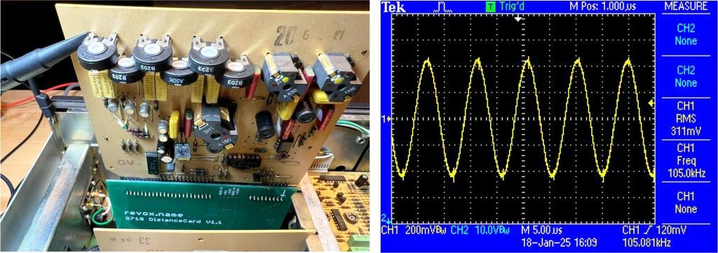 Figure 17. Oscillator board on extender card (left), final oscillator frequency after adjustment (right).
* Next, the record head azimuth alignment was monitored by feeding a low level 3.5 mV (-20 dBu on Peak Reading Meter), 10 kHz sine wave signal into the Line Input, with MONITOR switch set to TAPE position during tape Recording. Turning the record head adjustment screw by approx. 10 degrees CW was sufficient to align the phases of the Left and Right channels (Fig. 18).
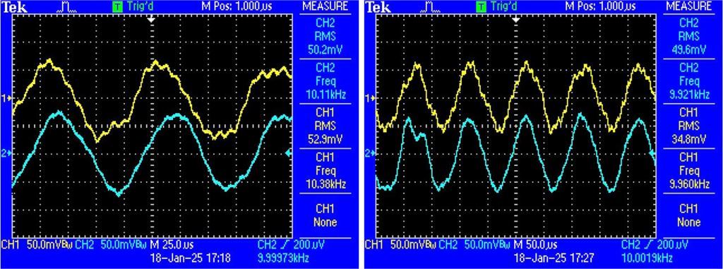 Figure 18. Record head azimuth before phase alignment (left), and after phase alignment (right).W&F measurements in recording mode
* Two test tapes were created by feeding a 3150 Hz sine wave into the Line Input and recording several minutes of signal to each tape.
* Using the same AnalogMagik setup as before, each test tape was played back to compute the AES Weighted Peak Flutter values.
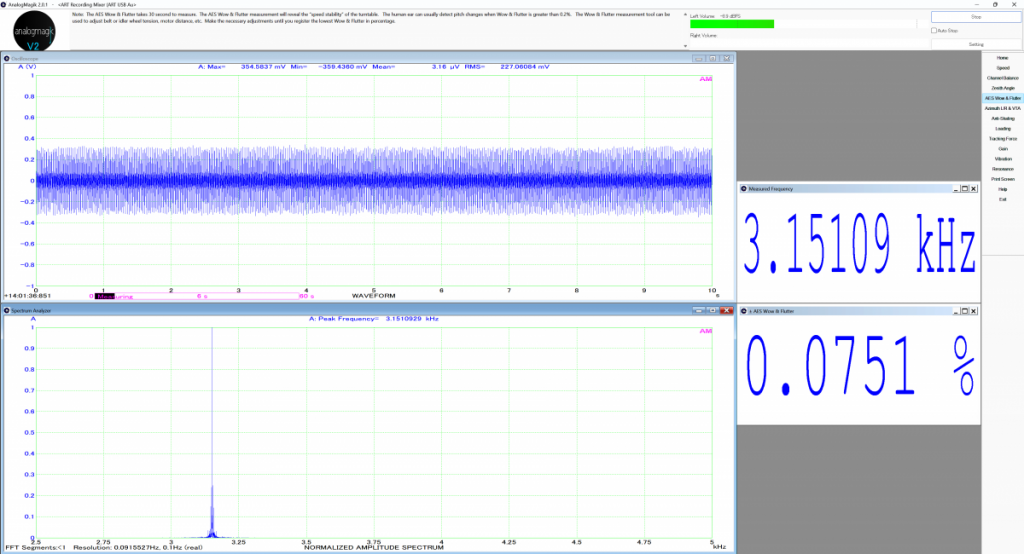 Figure 19. Example of an AES W&F measurement using Record The Master C60 test tape.
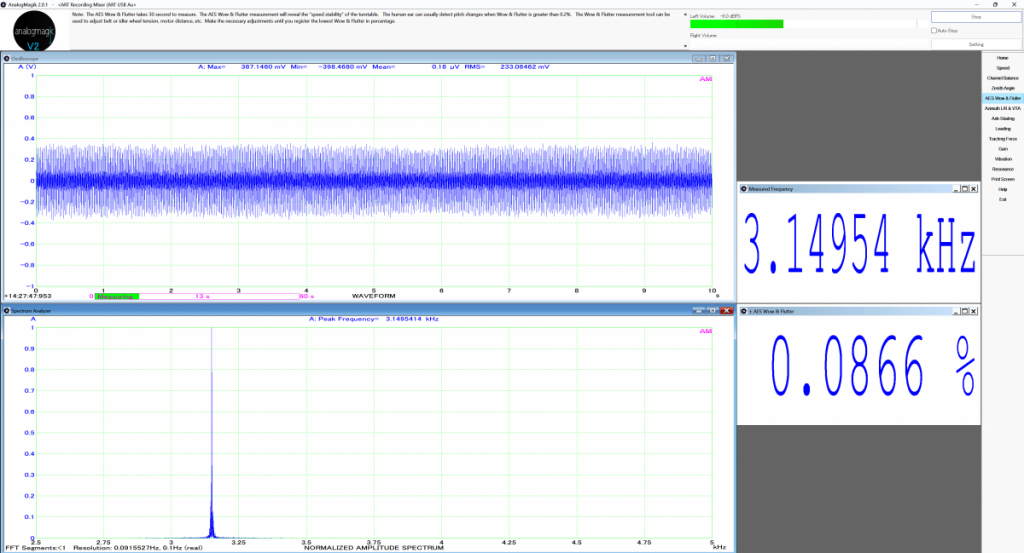 Figure 20. Example of an AES W&F measurement using Maxell UR60 test tape.
* The AES W&F values shown in Figures 19 and 20 agree closely with the previously computed AES W&F value displayed in Figure 15.
* As a final check, the WFGUI program was used to compute the Weighted RMS W&F values, one example using the Maxell UR60 test tape is shown in Figure 21.
 Figure 21. Example of a Weighted RMS W&F measurement using Maxell UR60 test tape.Summary of W&F results from recording mode
 Table 2. Results of W&F measurements from recording mode: Weighted Peak Flutter and Weighted RMS.
* As commonly seen, the Weighted RMS values in Table 2, in numerical terms, are about half the corresponding Weighted Peak Flutter values. Further details comparing Weighted Peak Flutter measurements vs. Weighted RMS measurements are described in report
"ReVox B710 MK1 Tape Deck - A Wow & Flutter Software Comparison Test".
* Reviewing the results obtained from this test, it can be said there was no detrimental effect from conducting the W&F tests in recording mode.
* Regarding which brand of cassette tape to choose, similar W&F results were achieved with both tapes, indicating either brand of tape would be suitable for this test.
What did this restoration accomplish? * While it took almost 2 years to complete this restoration, partly due to my first experience with a tape deck, my breaking the solenoid plunger (ouch), some delayed parts deliveries, and a random failure in the Reproduce Amplifier board (which I successfully repaired and posted to the AudioKarma "Tape" forum), pleased to report my B710 Cassette Tape Deck now looks, operates, and performs like it was new!
* And throughout this restoration process I certainly learned a lot about tape decks and the W&F measurement methods.
References* ReVox B710 service manuals:
https://www.reeltoreel.nl/studer/Public/Products/Revox/Revox_B710/* Technical Protocol No. 174 (Lubrication of sintered Bearings in Capstan Motors):
https://www.reeltoreel.nl/studer/Public/Products/Recording_Analog/_IMPORTANT%20LUBRICATION%20INFO/* Nagravox site for A/B710 Cassette Tape Decks,
https://nagravox.com/collections/revox-a-b710 * GennLab site for Cassette Alignment Tapes,
https://www.gennlab.com/alignment_cassettes.html* ReVox B710 MK1 Tape Deck Reproduce Amplifier - A Successful Repair,
https://audiokarma.org/forums/index.php?threads/revox-b710-mk1-tape-deck-reproduce-amplifier-a-successful-repair.1068548/* ReVox B710 MK1 Tape Deck - A Wow & Flutter Software Comparison Test
https://www.audiocircle.com/index.php?topic=190768.0* Extender Card: revox.name for B710 Distance Card,
https://www.revox.name/sell/b710distancePCB/* AES Standard - Method for Measurement of Weighted Peak Flutter of Analogue Sound Recording and Reproducing Equipment AES6-2008 (r2012). Copyright published by Audio Engineering Society, Inc.
https://aes2.org/publications/standards-store/?id=15* Download site for Alex Freed's WFGUI program,
http://www.ant-audio.co.uk/index.php?cat=post&qry=libraryAppendix* As mentioned in section History, while undergoing service by Studer ReVox in 1992 all applicable factory upgrades were implemented, bringing it closer to MK2 status (Table 3 and Fig. 22).
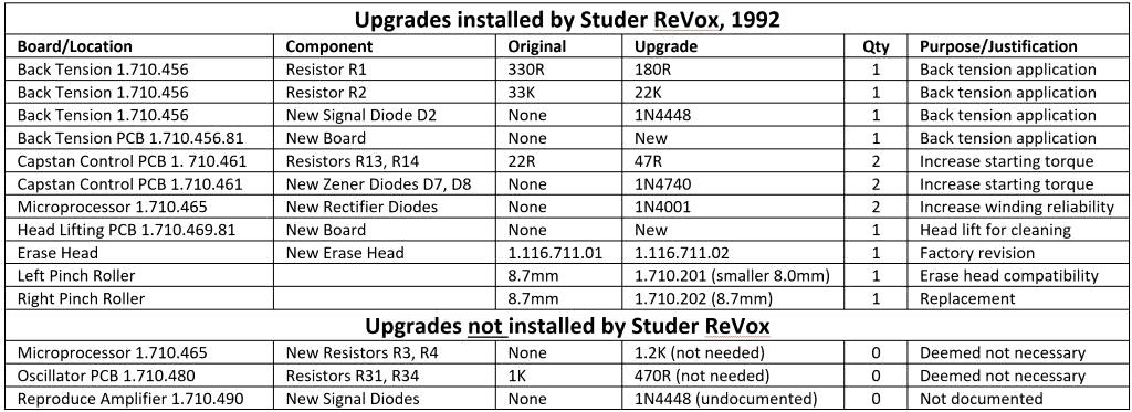 Table 3. Installation status of updates performed by Studer Revox Canada - February 1992
* Regarding the updates not implemented by Studer ReVox Canada.
*
R3 and R4 on Microprocessor board. After the wind-mode improvement from adding the twin 1N4001 Diodes, further improvement was deemed unnecessary by Studer Revox. However, that was over 30 years ago, and with the passage of time older cassettes had further aged suffering from increased internal friction. As per Studer Service Instruction SI 106/87, to further improve the wind-mode reliability I implemented the resistor modification as part of this restoration (Fig. 13).
*
R31 and R34 on Oscillator board. Studer Revox may have determined the bias level was sufficient with no need to increase it.
*
Signal Diodes on Reproduce Amplifier board. Not a documented/released update?
* Apart from saving me the effort of installing these updates, the work done in 1992 by Studer Revox Canada to my B710 early MK1 unit teaches some interesting information.
* Contrary to the title "
A710 Modifications" in the Studer Service Instructions SI 106/87, it appears the updates were indeed applicable to the B710 series. Examples from the Service Report (Fig. 22) list new parts related to the updates such as
"Diode (x2), Back Tension, Tension PCB, Head Lifting PCB". * The Service Report lists new parts installed
"1.710.201 Pinch Roller L" and "
1.710.202 Pinch Roller R" (diameter 8.0mm and 8.7mm respectively), together with new
"1.116.711.02 Erase Head". This makes sense as it follows the Studer ReVox Service Instructions section
"3.4.3 Adjusting the Erase Head".
"Version B710 MKI: Erase head 1.116.711.01 has been installed in the MKI versions. If replacement is required, erase head 1.116.711.02 is also used in these recorders. In this case, however, the left-hand pinch roller (diameter 8.7 mm) must be replaced by a smaller roller (diameter 8.0 mm, 1.710.201.00)." * A couple of interesting remarks about the Studer ReVox Canada Service Report.
I. Back then the sales price for original Studer ReVox pinch rollers seemed a bargain at CAD 9.75 and 9.10 for Left and Right respectively, about 6 Euros each at current exchange rates.
II. The labour charge for all repairs and upgrades was just 8-hours, explains a big difference in their expertise/experience vs. mine!
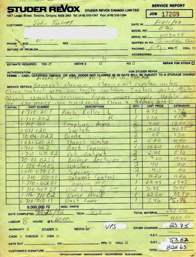 Figure 22. Studer Revox Canada, Service Report from February 1992 - B710 serial number 003055
<End of report>