Coupling Cap Values for Quicksilver Amps

0 Members and 2 Guests are viewing this topic. Read 8599 times.

Russtafarian

  • Full Member
  • Posts: 1118
  • Typical reaction to the music I play
Coupling Cap Values for Quicksilver Amps
« on: 2 Nov 2007, 07:44 pm »
Hey Folks,

Haven’t posted here in a while.  With my wife in grad school and my boys playing football, I haven’t had much time for audio projects.

I want to upgrade the coupling caps in my Quicksilver mono amps.  Here’s the schematic.


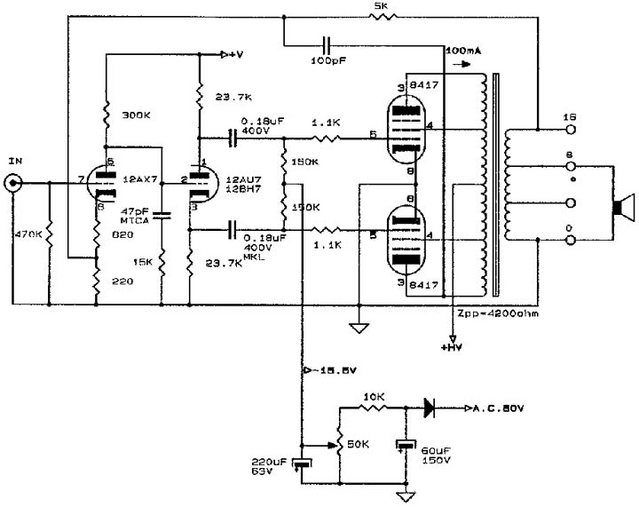
Each channel uses two 0.18uF caps. The resistor setting the input impedance of my amp is 100kohms, not the 470kohms shown in the schematic. 

I would like to change the value of the caps to increase the high pass filter hinge frequency to around 80Hz. 

With this circuit, will the formula F= 1/(2piRC) tell me the HPF frequency, which in this case would be 1/(2pi*100,000ohms * (0.18uF + 0.18uF)) = 4Hz? 

Assuming that is correct, can I change the value of the caps to 0.01uF to get a HPF frequency of 80Hz?

Or am I completely misunderstanding the circuit here and should leave coupling cap values as is?

Thanks for your help.

Russ

scottnixon

  • Jr. Member
  • Posts: 80
    • http://www.scott-nixon.com
Re: Coupling Cap Values for Quicksilver Amps
« Reply #1 on: 2 Nov 2007, 08:01 pm »
Leave the amp as is. Just add an input cap of about 0.02uf  between the input jack and your 100k load R.

PaulHilgeman

Re: Coupling Cap Values for Quicksilver Amps
« Reply #2 on: 2 Nov 2007, 08:49 pm »
By my calcs, 0.018uF is going to get you 88Hz, 0.022uF will get you 75Hz.

Ideally you would want .0199uF.

Are you trying to integrate a set of sealed mains with a subwoofer?

You might want to add another resistor in there and make it a true 2nd order HP filter, that way you would get roughly a 4th order roll-off out of the speaker, which would be easier to integrate with most sub woofer amplifiers.

-Paul

Russtafarian

  • Full Member
  • Posts: 1118
  • Typical reaction to the music I play
Re: Coupling Cap Values for Quicksilver Amps
« Reply #3 on: 2 Nov 2007, 11:07 pm »
Thanks for the help Scott.  That's easy enough to implement.

Paul, you're right, I am trying to integrate mains with subs and I will probably use a 0.022uF cap.  How can I make it a 2nd order filter?  What value resistor and where would I put it?

Thanks again.

Russ

scottnixon

  • Jr. Member
  • Posts: 80
    • http://www.scott-nixon.com
Re: Coupling Cap Values for Quicksilver Amps
« Reply #4 on: 3 Nov 2007, 12:33 am »
To do a 2nd order you need another cap and resistor ... and it may present another issue.  Add another cap 0.2uf in front of the .02uf this time and 10k to ground at node of the 2 caps.  No free lunch though as now your total load the preamp sees is ~9k, that paralleled with the sub amp, it goes lower.  May not matter depending on the preamp.

Russtafarian

  • Full Member
  • Posts: 1118
  • Typical reaction to the music I play
Re: Coupling Cap Values for Quicksilver Amps
« Reply #5 on: 4 Nov 2007, 05:33 am »
Cool.  I can do that.  I'll build a few filter variations that I can plug into the amp's rca input.  Once I settle on the frequency and slope, I'll put the filter inside the amp.

Thanks again for your help.

Russ

KBK

  • Jr. Member
  • Posts: 102
    • Teo Audio
Re: Coupling Cap Values for Quicksilver Amps
« Reply #6 on: 4 Nov 2007, 11:16 pm »
I'd stick to doing the mod as far down the chain as possible, if this be for the mains. Or, conversely..going to a really high quality cap at the input. 6 uvvv one.. harf doz uh the uther.

But it would likely be best to stay out of the active circuitry and mod the input. dang it. He's right. mod the input. But you will really have to know your impedances that will be involved in this situation.

GBB

Re: Coupling Cap Values for Quicksilver Amps
« Reply #7 on: 5 Nov 2007, 01:39 am »
Russ,
I used to own a pair of the QS 8417 monoblocs - they're nice amps.  I'm not sure if you've experienced it, but they are quite picky about which 8417 tubes can be used in them.  Sylvania and Philips 8417s were good but the GE 8417 would often run away.  One of the output tubes would start hogging the current and the plates would get bright red and then the tube would die if you didn't turn it off fast.
It turns out there's an easy fix for this since the cause is that the GE 8417s have to much grid current.  That grid current through the 150K grid resistor makes the tube turn on too hard.
To fix it - just change the grid resistors from 150K to 47K ohms.  To keep roughly the same low frequency cutoff, you then increase the 0.18uf 400v caps to 0.47uf caps. 

Here's a link to a page from Triode Electronics detailing this fix along with other changes you can make to the amp.

http://www.triodeel.com/8417.htm

---Gary
p.s.  I think I might have a spare quad of 8417 lying around if you need some. 

Russtafarian

  • Full Member
  • Posts: 1118
  • Typical reaction to the music I play
Re: Coupling Cap Values for Quicksilver Amps
« Reply #8 on: 5 Nov 2007, 10:15 pm »
Hi Gary,

The runaway 8417 scenario is one I'm familiar with.  I got these amps from a friend who, after blowing through too many output tubes and and an exploding PS cap, finally gave up on them.

I've recapped and performed some of Ned's mods on the amps and am presently running them with 6550s.  I kinda gave up on 8417s after getting frustrated with ebay-go-round acquisition process.  Though the 8417s certainly had that midrange magic, they (at least the ones I have) sounded a bit murky compared to 6550s.  Just my opinion, but these amps with 6550s sound more magical than some of the other 6550/KT88 PP amps I've heard.  Don't know why but I like it. 

BTW, thanks for your SB3 mod posts a while back.  Very helpful to me.

Russ