My Piccolo

0 Members and 1 Guest are viewing this topic. Read 4426 times.

ecir38

  • Jr. Member
  • Posts: 119
My Piccolo
« on: 2 Sep 2007, 09:53 pm »
almost done  :D


Bill Epstein

Re: My Piccolo
« Reply #1 on: 3 Sep 2007, 02:21 am »
Wow!

What a clever design. Do your own metal work?

ecir38

  • Jr. Member
  • Posts: 119
Re: My Piccolo
« Reply #2 on: 3 Sep 2007, 02:48 am »
I purchased the encloser here.
http://www.lmbheeger.com/products.asp?catid=27
Model# KB4-7

The enclosure is a pretty good quality and they have great service and fast shipping. 

analog97

  • Full Member
  • Posts: 373
Re: My Piccolo
« Reply #3 on: 3 Sep 2007, 04:25 pm »
Flat out beautiful!!  I'm not sure of the rules for the JH "DIY" of the month prize, but this seems to qualify.  Congratulations!  I am breaking another Commandment..."Thou shalt not covet thy neighbor's PICCOLO"......

ecir38

  • Jr. Member
  • Posts: 119
Re: My Piccolo
« Reply #4 on: 4 Sep 2007, 04:53 pm »
Jim, i have not installed the terminal shields yet. Do you have a recommandation how they should be installed for this layout?

Would connecting pin 1 of U1 to ground be recommended for this layout?

Thanks

tubesforever

  • Full Member
  • Posts: 441
Re: My Piccolo
« Reply #5 on: 6 Sep 2007, 10:47 pm »
Very nice.  I absolutely love your screw in posts for the RCA's and the resistor sockets.

First class all the way.

ecir38

  • Jr. Member
  • Posts: 119
Re: My Piccolo
« Reply #6 on: 6 Sep 2007, 11:43 pm »
Yea I know I went a little terminal block crazy. The RCA t-blocks can be purchased at digikey or mouser and have a 5mm spacing with the center terminal removed. The solder pins fit right next to the outside of the two trace holes. I experienced with just soldering the wire straight to the pcb but wasn't comfortable with how that came out.     

RCA terminal block link
http://www.mouser.com/search/ProductDetail.aspx?R=651-1935174

Back at ya for the very nice for your build  :thumb:. When you get some time you should post some pics over here. Look forward to your impressions after your trip.

Jim can you help out with reply #4?

« Last Edit: 2 Oct 2007, 12:24 pm by ecir38 »

hagtech

Re: My Piccolo
« Reply #7 on: 10 Sep 2007, 06:53 am »
Quote
i have not installed the terminal shields yet

Yeah, I guess I don't know what you mean by terminal shields.  The wiring in the photo looks ok, as long as it is in the metal box.  Gain is not tremendous, so there's probably not too much danger of coupling between output and input.

jh

ecir38

  • Jr. Member
  • Posts: 119
Re: My Piccolo
« Reply #8 on: 10 Sep 2007, 08:18 pm »
Sorry that I wasn't clear. I was referencing the terminal shields with the wings facing outward like in the pic below. I am not shure of their purpose and was wondering if they would be needed in my application since i am not using the output jacks on that side of the board. I guess it wouldn't hurt anything if I install them as shown in the pic below.


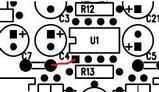
You state this in the manual.

"If you do not build in the recommended stock chassis configuration, you can reduce the
potential for high frequency noise contamination by forcing the dc-dc converter to
operate at a higher frequency. Connecting pin 1 of U1 to ground does this. Add a jumper
on bottom of board, as shown below."


I was also wondering if you thought I would benefit from this for the layout i am using in the original post?

Thanks

hagtech

Re: My Piccolo
« Reply #9 on: 10 Sep 2007, 11:01 pm »
It's good to force the higher frequency operation.  The classic 7662 chips do not have this feature, and I designed the PICCOLO to operate with them anyway.  The 'shields' are good in that they act as electronic field blocks between the output circuits, rotary switch, and the power supply chip.  You'll also not the RCA jacks are rotated such that the ground covers it's center conductor.  Much going on in there that isn't obvious.

Anyway, keep the shields in place, do the pin 1 trick. 

jh

ecir38

  • Jr. Member
  • Posts: 119
Re: My Piccolo
« Reply #10 on: 10 Sep 2007, 11:15 pm »
Sounds great thanks Jim!

The Piccolo is basically finished other than the above. Painted the enclosure satin black and am waiting for the stuff I ordered for the decals which should arrive friday. Will post finished pics next week which should be nice if the decals come out the way I plan.

Thanks again

ecir38

  • Jr. Member
  • Posts: 119
Finished Pics
« Reply #11 on: 19 Sep 2007, 06:03 pm »
The decals were harder to do than building the Piccolo. Pictures aren't the best sorry.


« Last Edit: 28 Sep 2007, 01:15 pm by ecir38 »

PatOMalley

  • Full Member
  • Posts: 303
  • This text is personal
    • http://home.comcast.net/~omaille/audio/home.html
Re: My Piccolo
« Reply #12 on: 19 Sep 2007, 06:21 pm »
that looks nice. Real nice. direct matching of the internal cart DC is what you are after?

Where did you get the decals?

ecir38

  • Jr. Member
  • Posts: 119
Re: My Piccolo
« Reply #13 on: 19 Sep 2007, 06:40 pm »
that looks nice. Real nice. direct matching of the internal cart DC is what you are after?

Where did you get the decals?

I don't know what you are asking in the first question.

The decals are DIY from http://www.pulsarprofx.com/index.html
The decals worked but they make it look easier than it is. I had to be pretty persistant and it still could have been better. If anyone is interested in this process let me know before ordering. I didn't buy the kit i ordered just what i needed.

amandarae

Re: My Piccolo
« Reply #14 on: 19 Sep 2007, 06:53 pm »
that looks nice. Real nice. direct matching of the internal cart DC is what you are after?

Where did you get the decals?

I don't know what you are asking in the first question.

The decals are DIY from http://www.pulsarprofx.com/index.html
The decals worked but they make it look easier than it is. I had to be pretty persistant and it still could have been better. If anyone is interested in this process let me know before ordering. I didn't buy the kit i ordered just what i needed.

I think, he was referring to different values of the loading resistors as compared to the "stock" ones.


ecir38

  • Jr. Member
  • Posts: 119
Re: My Piccolo
« Reply #15 on: 19 Sep 2007, 07:03 pm »
I changed the resistors values to hopefully work nice with a AT33PTG.

wdi

  • Jr. Member
  • Posts: 38
  • know just enough to be dangerous
Re: My Piccolo
« Reply #16 on: 27 Sep 2007, 04:48 pm »
OK, I'm stopping to ask directions.....
I don't see the photo is the original post, but apparently everyone else can. I do see the one a few posts down with the circuit board on the calendar. I noticed this on several threads....is there a setting I need to change to see all of the photos, or is it a link that I'm overlooking?

Sorry this isn't directly related to the topic.

thanks,
Bill

ecir38

  • Jr. Member
  • Posts: 119
Re: My Piccolo
« Reply #17 on: 1 Oct 2007, 07:17 pm »
I decided to redo the terminal blocks I used for resistor loading. They proved to be not very user friendly especially with larger resistors like the RN Vishay / Dale.

This way should prove to be easier for anyone that would like to try and tackle this. This idea originated from seeing how tubesforever came about making the resistors removable on his Piccolo as seen in the pic below. Thanks tubes for coming up with another way to go about replacing the resistors without soldering.


The pics are self explanatory. The only additional mod was I cut two pieces of .040” unclad FR4 board 1/2” x 11/16” and hot glued them to the housings to make one assembly. Any similar material can be substituted. This was done after installing the header and before installing the connectors. I used a label maker to identify these in the future.     


Here are the links for the parts I used.
Housing
http://www.mouser.com/search/ProductDetail.aspx?R=10-11-2063virtualkey53810000virtualkey538-10-11-2063
Header
http://www.mouser.com/search/ProductDetail.aspx?R=538-22-03-2061
Socket Connectors
http://www.mouser.com/search/ProductDetail.aspx?R=538-08-50-0005

« Last Edit: 2 Oct 2007, 12:12 pm by ecir38 »