I occasionally think about taking lots of photos to make some tutorials, but as soon as I start working I forget about the photos.
On this occasion, the customer was with me and wanted to document the process. While he took photos, I also took a few of my own. I'll share a few with hopes that it helps someone else.
Here are first steps which shouldn't require photos (plus I hadn't taken any yet).
1- The pair of speakers is placed lying down and elevated on a table (padded w/ blanket or towel) so that the legs/feet can be removed (2 screws each leg). The speaker panel does have threaded inserts for the legs so no hazard to the soft mdf panel.
2- remove the side edge strips if present (this model had no edge trim, but many do). Start at the bottom with a gently pry tool and wedge the trim outward away from the panel. You don't have to remove the whole trim piece, just pry out the bottom portion of trim, enough to raise the cloth sock above the crossover opening and panel connections (maybe 2 feet max?)
3- remove the 4 screws that secure the aluminum input panel which houses the binding posts.
4- Remove the staples from the bottom edge of the mdf panel.
5- Slide up the sock far enough to access the crossover opening and the connections at the bottom of the panel (stretch the socks opening for the input panel over the input panel that has already been disconnected, to get it past that point.
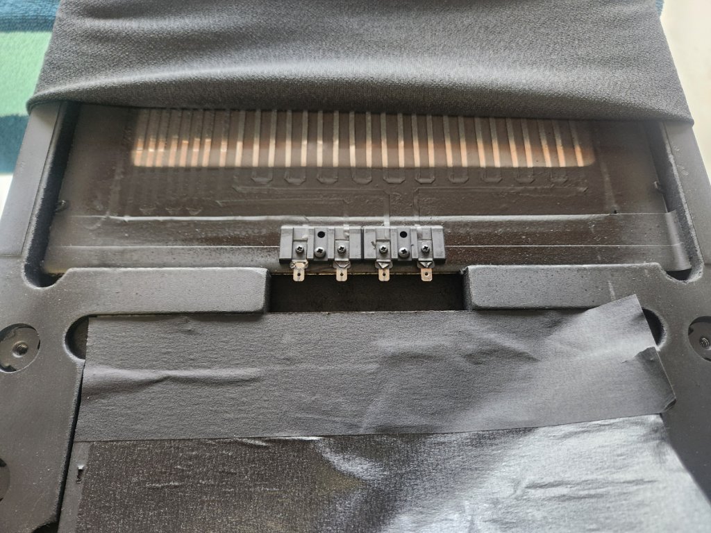
The owner is holding the connections panel above as I grab my first picture. I'm kind of amazed at all the little steel terminals and one of the jumpers even seems to be a thin piece of steel cable?.
6- No need to try to sort any of this out or identify connections, just cut the wires and disconnect everything you see. None if it gets reused. Even if you wanted to reuse the panel, you would still want to start over with new wires and connections.
7- Remove the crossover wire connections from the bottom of the front speaker panel. A little pinch with pliers, pulling down on the wire and the tabs should slide off easily.
8- Cut any zip-ties holding the original crossover, cut any wires as short as you can, to get things out of your way.
9- These metal terminal tabs (steel?) are attached to the backer board with a crimp over, similar to a rivet or snap hole. If you grabbed it with pliers and twisted and pulled repeatedly for several minutes it would eventually tear free from the backer board. I found it easy to just drill through the terminal post. Drill a hole right through where its crimped onto the panel.
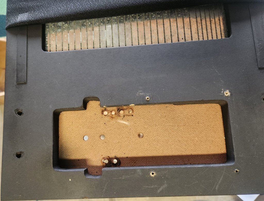
10- All the old stuff is gone, pat yourself on the back. It already looks better.
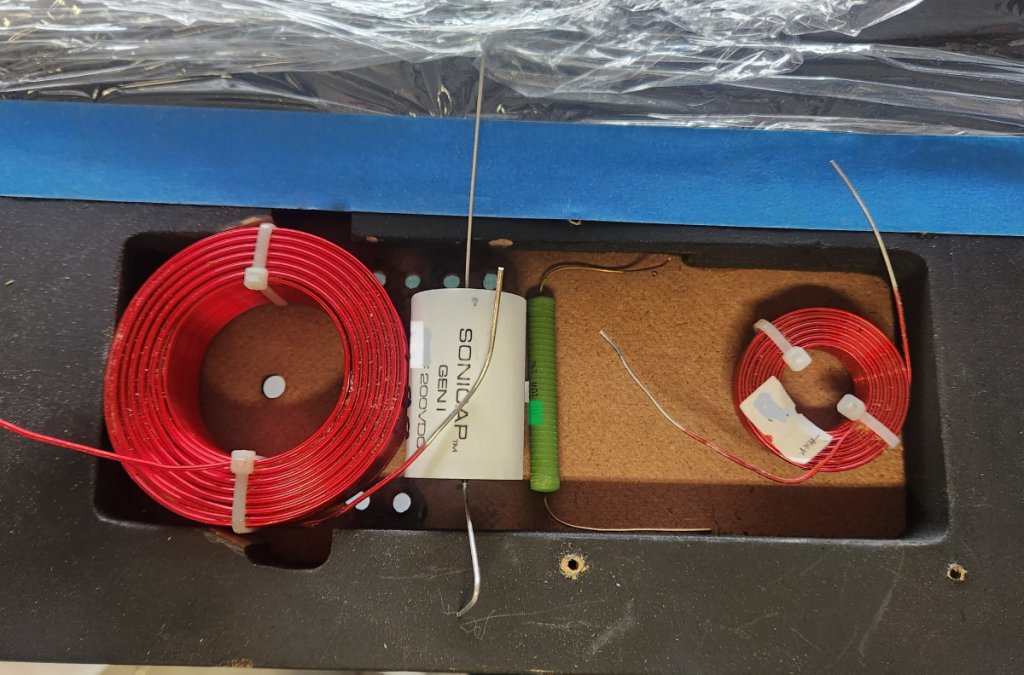
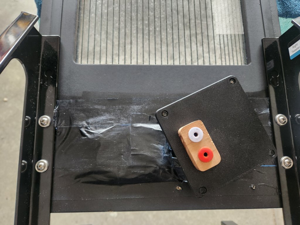
11- Dry fit your new crossover components. Also test fit the 3d-printed panel provided in the kit, with the female tube connectors or your binding posts to make sure the new binding posts have room for their internal connections. I found that the predrilled screw holes on the new panel lined up perfectly with the existing holes from the original aluminum panel. If you wanted to, you could relocate this panel as needed and drill new mounting holes in the speaker panel.
It is in this dry-fit stage that you will realize that the depth needed for the tube connectors exceeds the internal depth available within the mounting space. For that reason, you will see that I simply added a 3/4" scrap on the outside of the printed panel, which added enough additional depth. This is a scrap piece from a walnut cutoff and any material could be used. A 3/4" thick mdf scrap or similar, painted black would also be fine. The customer was with me and he was happy with the small contrast of the walnut scrap so that's what I used.
note- You will see near the top and bottom edges of the largest inductor (at white zip-tie location) that I cut a small corner off of the mdf panel corner. Please don't try to cut into this panel with a router-bit. It's overkill, will make a ton of dust and is certainly less stable. This mdf is soft and a simple wood chisel made easy work of shaving off a slice from each corner. No hammer needed, just light downward pressure with the hand chisel and the edges can be shaved off easier and quicker then it would take to install a router bit and adjust the depth. I shaved the corners just enough so that the large inductor could slide all the way to the left edge of the opening. If I was doing it again I would actually take off an additional 1/8" or up to 1/4" from the left panel edge where the left edge of the inductor makes contact. You don't have to remove material from that full edge, just the center of it where the inductor makes contact. By shaving off another 1/8" to 1/4" you will have a little more clearance space between the other side of the large capacitor and the new 3d-printed cover panel. It's a tight fit and even an 1/8" more would have made it even easier.
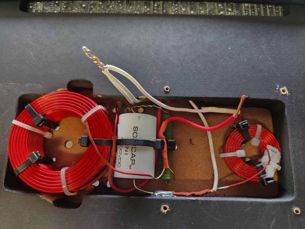
12- I'll add a layout drawing later to show the connections, but this layout is very simple, I planned out the wire connections, then drilled new holes for the new zip-ties, secured all the components, and then soldered everything together. I'm possibly more comfortable with soldering in tight places then most, which probably works against me. I always secure everything and then solder. In reality, it would be easier to solder all the pieces out in the open, and then insert and secure it after solder. Imagine loosely securing the pieces with tape to a scrap board in the same orientations, solder it there unobstructed, then drop it into the opening and secure with zip-ties. That would have been easier.
This is one of the before photos. There is no magic here. This is painters tape that was spray painted flat black at the factory. The same type of painted tape layer is present on both sides of the panel. It is purely cosmetic with the only purpose of providing a uniform color when viewed naturally with the original sock installed. There is no need to try to salvage it. New painters tape strips or anything similar with a quick hit of spray paint will restore that black concealment easily.
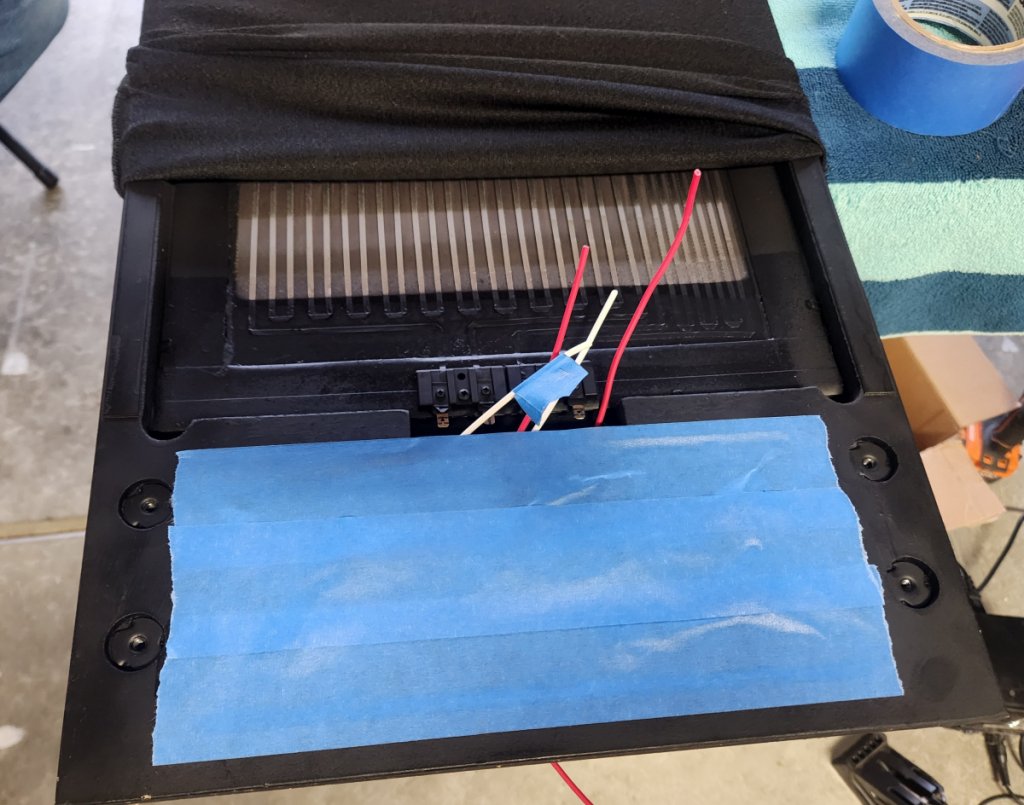
13- When making your connections in step 12, just leave a couple inches of extra length on each connection. Here with the crossover fully installed I simply held each internal wire connection over the terminal connection block where they connect to the speaker panel itself. I cut each wire to final length with no more that an extra inch, trying to avoid having to stuff more extra wire back into the opening than necessary.
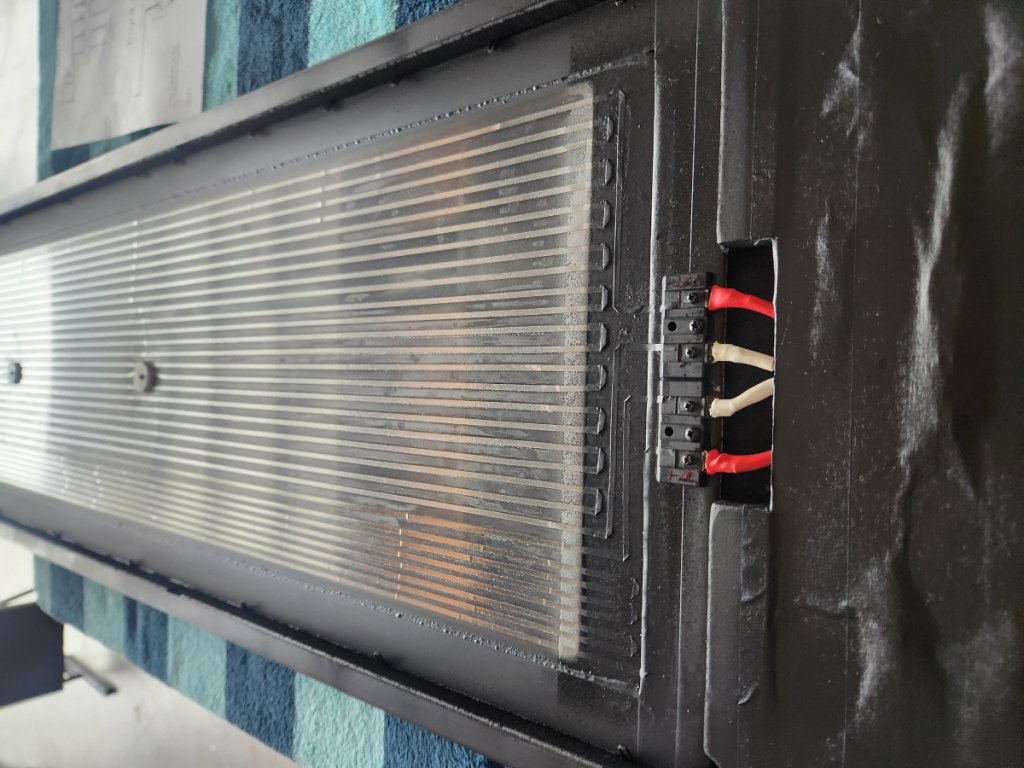
14- I chose to solder the connections instead of using push-on tabs, but tabs could be used. I don't know how fragile or heat sensitive the glue is that holds the ribbon to the panel but to prevent heat transmitting up the ribbons and possibly weakening that adhesive, I used a wet paper towel placed over the terminal block with only the actual tabs left exposed. After soldering each connection I lifted the cloth and could feel the terminal block and the ribbons remained cool with no excess heat passed up the ribbon. Then dry any water immediately after solder. The customer wanted to avoid using the tabs but each person could make that decision on their own to solder that connection or not.
(In this photo above, two of the connections were reversed. As indicated in step 16, be sure to test before staplng the sock back on, 1st speaker was connected out of phase and I had to redo the connections)
15- After everything is soldered up, re-cover with tape and a touch of black paint. On the back side, you will have to tear or cut a small opening in the tape to make your internal wire connection with the female tube connectors. create a small opening right where the back side of the tube connectors would enter into the mounting space. Nudge your crossover wire connections to that location and solder to the connectors.
16- Test your speakers at this time, before re-stapling the sock. I messed this up on the first speaker. I reversed the positive/negative connections to one of the panels. I called Danny and he was very helpful in helping me sort out the correct connections on the panel. Properly identifying those connections which are not labeled and have no data published from the manufacturer was the largest obstacle in this assembly.
note- The paint I already had was a semi-gloss, not flat like original, but it still was not visible through the cloth sock.
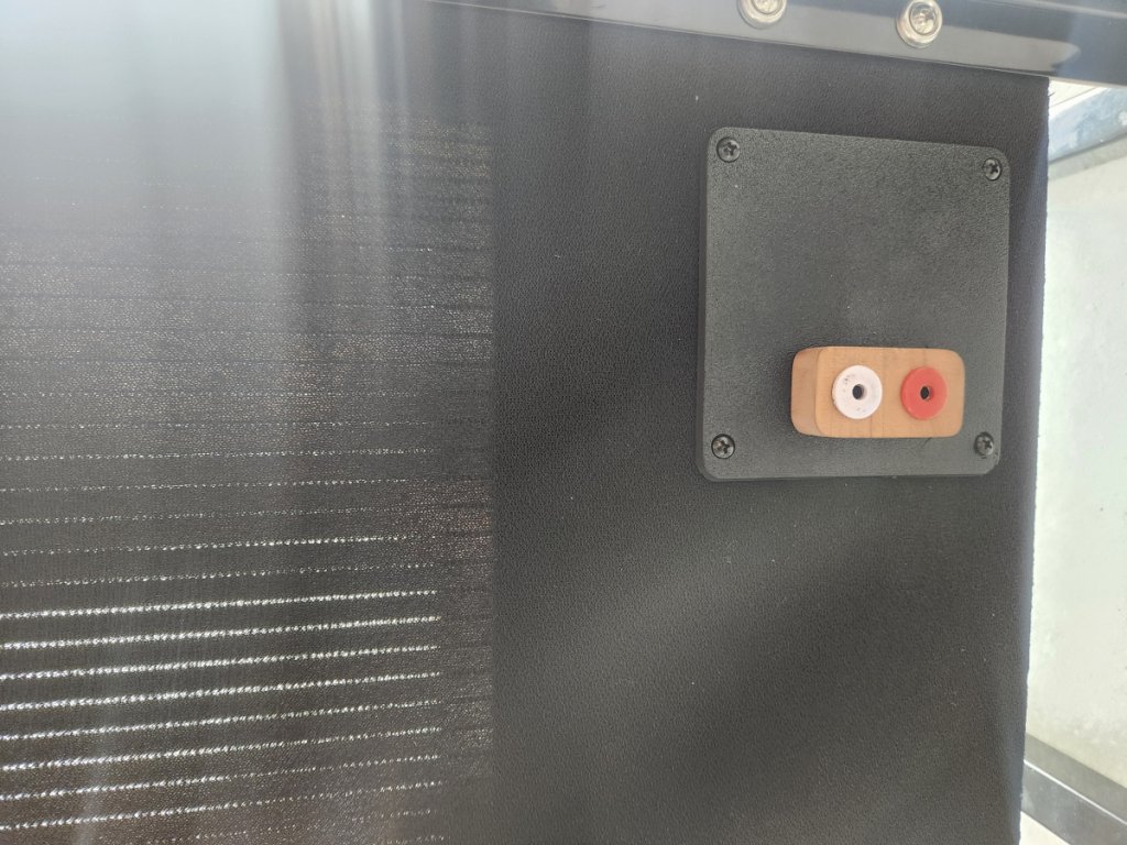
16- Slide the cloth sock back down over the bottom part of the panel, and stretch the rear panel opening in the sock, over the 3d-printed replacement rear panel. Align the holes in the sock from the four panel screws and attach the new rear connector panel. Stretch the cloth sock down so that the holes for the feet/legs roughly align and re-staple the sock to the bottom of the speaker panel. I used a T-50 stapler and then gently hammered the staples their final distance home.
17- Reattach the legs/feet. Enjoy your speakers.
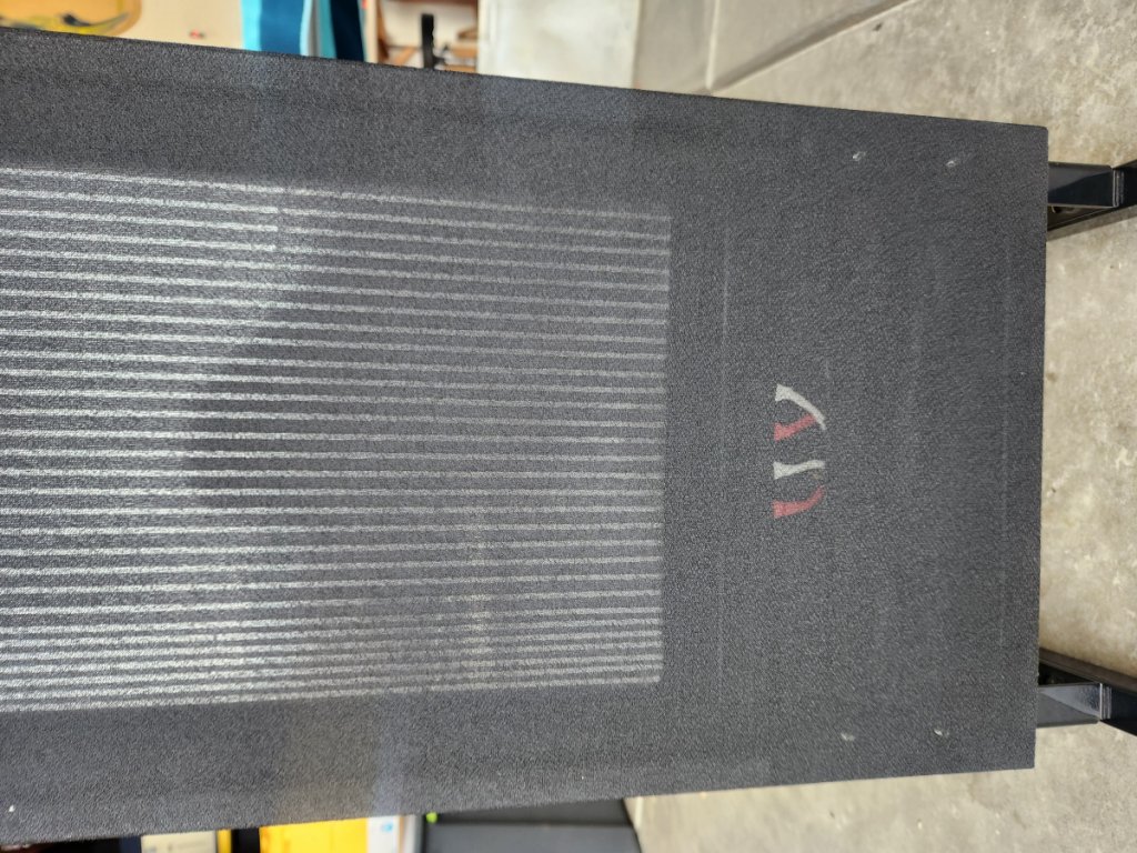
I offered the customer that I would cover that front visible area where the red/white colored wires show, but he really liked the contrast and felt that it was a small visible hint that the speaker had been upgraded. If you wanted to conceal that area visibly, you could spray paint over the wires as-is when you paint the tape (same as the factory does) or add an additional piece of tape over the wires that gets painted at the same time. In person, the visibility that you see through the sock (wiring and the speaker panel itself) is much less in person than what it appears in this photo.