Does anyone have first hand knowledge regarding the internal structure of the Cornwall III vis-a-vis bracing & acoustic insulation?
I ended up with the CW III speakers in one of those too good a deal to pass up scenarios. My main system has a pair of "W" OB servo woofers laid horizontally with Magnepan MMGs on top of them.
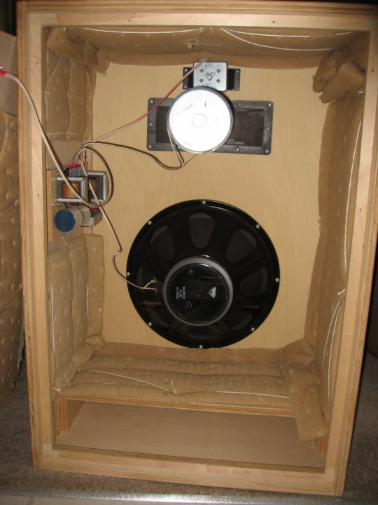
I dont have any first hand experience sadly, & I couldn't find many pictures of the Cornwall III internals, but I have found internal pics of the Cornwall I, 1.5 & II, and there's very little bracing, if any, in them, mostly just some small braces in the corners that aid in assembly. There is a video looking inside the Cornwall IVs tho.
The Cornwall III & IV seems to have 2 large braces just above the woofer, and some pics of the CWIII's being built show the same braces. And there's likely a shelf just above the ports similar to the ones in the CWI & II.
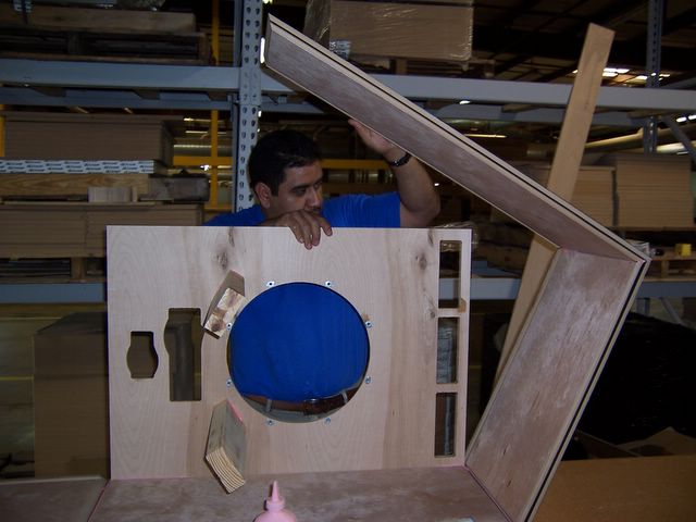
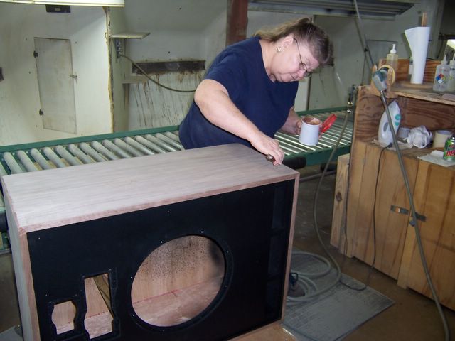
Inside of a Cornwall "1.5"
I would be buying what I need. My thought is, if all we are trying to do is to tame resonances, would adding a small amount of mass on the panels which resonate change the frequency they are excited by to outside the bandpass of the driver?
Adding mass to all of the surfaces should absolutely do what needs to be done, but if I don't need to do the additional work and the additional expense it's a win-win (work smarter not harder).
You likely wouldn't be needing more than 2 10"x14.5" sheets (depending if you oder by sheet or by roll) per speaker, and it'll be most effective on any large/flat surface area. Plus anything left over can be used to dampen the woofer frame. I ordered a pack of 10 sheets off Amazon for about $20 and have used it for several different projects, and I still have some left over for future projects.
https://www.amazon.com/dp/B01KZ5X7KO/ref=cm_sw_r_cp_apa_fabc_spa7FbRXXFHJJ?_encoding=UTF8&psc=1