Testing capacitors

0 Members and 1 Guest are viewing this topic. Read 1273 times.

Bumpy

  • Full Member
  • Posts: 444
Testing capacitors
« on: 27 Feb 2020, 01:35 pm »
I have a capacitance tester.

I also have some caps that don't seem to have any polarity markings, so I am guessing they are bi polar. These measure the same value whichever way I connect them to the meter.

For a reality check, would a polar capacitor measure full value in one direction and not the other?

Speedskater

  • Full Member
  • Posts: 2680
  • Kevin
Re: Testing capacitors
« Reply #1 on: 27 Feb 2020, 01:39 pm »
Only electrolytic capacitors have polarity markings.
While some film capacitors have a marking indicating the outer layer.

Bumpy

  • Full Member
  • Posts: 444
Re: Testing capacitors
« Reply #2 on: 27 Feb 2020, 05:04 pm »
Thanks for the reply, but I'm not sure that answers my question?  :D

FullRangeMan

  • Volunteer
  • Posts: 20041
  • To whom more was given more will be required.
    • Never go to a psychiatrist, adopt a straycat or dog. On the street they live only two years average.
Re: Testing capacitors
« Reply #3 on: 27 Feb 2020, 06:20 pm »
This may help:
https://www.ifixit.com/Wiki/Troubleshhoting_logic_board_components
Second paragraph are about cap tests.
« Last Edit: 27 Feb 2020, 09:55 pm by FullRangeMan »

Speedskater

  • Full Member
  • Posts: 2680
  • Kevin
Re: Testing capacitors
« Reply #4 on: 27 Feb 2020, 08:49 pm »
The electrolytic capacitor polarity markings are for connections to the DC supply.
The capacitance test is an AC test so the value will be about the same either way.
Not many bi-polar electrolytic capacitors in the world.

Bumpy

  • Full Member
  • Posts: 444
Re: Testing capacitors
« Reply #5 on: 28 Feb 2020, 04:40 pm »
The electrolytic capacitor polarity markings are for connections to the DC supply.
The capacitance test is an AC test so the value will be about the same either way.

So if the test regime cant differentiate polar from bipolar caps, I need to phrase the question in another way.

If a polar cap is put in a speaker high pass filter the wrong way round what will I observe?

JakeJ

Re: Testing capacitors
« Reply #6 on: 28 Feb 2020, 05:16 pm »
The music will come out backwards!


OK, just yankin' yer chain.  It may sound off as in the driver it is used for, say the tweeter, may have lower output than it should.

Steve

Re: Testing capacitors
« Reply #7 on: 6 Mar 2020, 05:08 am »
So if the test regime cant differentiate polar from bipolar caps, I need to phrase the question in another way.

If a polar cap is put in a speaker high pass filter the wrong way round what will I observe?

Hi Bumpy,

I am going to keep my reply very simple for the newbies out there.

Using a polar capacitor (almost exclusively wet type) in a speaker crossover with an AC musical signal will destroy the capacitor. Under high currents, the capacitor could even explode.

For the tweeter, the bipolar capacitor forms a high pass filter.

However, with a polar capacitor, the high pass filter only occurs during 1/2 the musical signal. The other half of the musical signal, the capacitor becomes nothing  more than a small value resistor, to all frequencies.

Cheers

steve


mboxler

  • Full Member
  • Posts: 300
Re: Testing capacitors
« Reply #8 on: 6 Mar 2020, 03:11 pm »

I am going to keep my reply very simple for the newbies out there.


I'll put myself in this category, but...

Most, if not all, single supply amplifiers place a high value polarized capacitor just before the speaker terminal.  This cap is in series with the crossover and couples the entire current between the amp and the speaker.  Why don't these caps explode?

Mike

Steve

Re: Testing capacitors
« Reply #9 on: 6 Mar 2020, 04:31 pm »
I'll put myself in this category, but...

Most, if not all, single supply amplifiers place a high value polarized capacitor just before the speaker terminal.  This cap is in series with the crossover and couples the entire current between the amp and the speaker.  Why don't these caps explode?

Mike

Correct Mboxler, there is a DC component at that type of amplifier's outputs that must be blocked from the
speaker terminals, and speaker. So one places a capacitor to block the DC voltage but allow the AC musical signal to pass through the crossover capacitor.

As a single DC supply amplifier, we need to first realize that the DC voltage can never go below zero volts with reference
to ground, thus the DC blocking capacitor is never reversed "biased" to below zero volts/negative volts.

Here is a schematic that I hope will help.
 

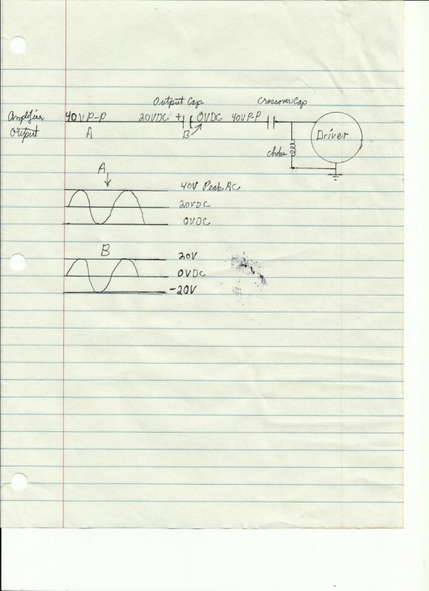
Point A, is the output musical signal (40 volts peak to peak, maximum output) and 20 volts DC. The AC musical signal "modulates" the DC voltage. The AC voltage varies with the 20 volts as the reference. As such, the voltage never goes below zero volts as the amplifier will start clipping. Peak voltage is plus 40 volts.

After we block the DC voltage, we have graph B. Notice there is no DC voltage at the right/crossover capacitor. The
reference for the AC musical signal is now zero volts. The AC voltage can now swing in to the negative region, to -20 volts.
This negative voltage will destroy our polar crossover capacitor. In fact, in the negative voltage region, the polar crossover capacitor will resemble a small resistor, passing all the frequencies, not just the highs. This will probably destroy our
tweeter as well.

Hope this helps.
steve


Bumpy

  • Full Member
  • Posts: 444
Re: Testing capacitors
« Reply #10 on: 7 Mar 2020, 12:38 pm »
Some good stuff here. Here is specifically why I ask.  In the picture you will see 2 caps - both are for experiments in an open baffle crossovers.

1. The grey cap is Russian PIO and is to be used as a high pass filter.
2. The black cap is very low value and will be tried as a bypass cap elsewhere. It has no markings at all other than a long and short tail.

Am I OK to assume they are both non polar?