Below is a link to a white paper I initially wrote in October of 1997, and recently updated. Although basic with little math, my paper deals with multiple purposes and considerations when designing the highest quality power supply for preamplifiers, and Class A, AB amplifiers.
Not only does the power supply have to provide pure DC, but also minimize any artificial artifacts from the AC line such as noise, RFI, but also deal with the musical signal at the other end. A power supply is much more difficult to design than most think. It is not just a couple of equations, but also includes parts quality.
http://www.sasaudiolabs.com/theory7a.htmFor those who need a little more help, here is some simplified information, some from my old Engineering textbook, Semiconductor and Tube Electronics by James Brazee, and RCA Radiotron Designers Handbook, written by 26 electrical engineers. I am an electronics engineer.
Let me first state that it is amazing how good the sound can be when a truly great power supply design is used with a great design and highest quality parts. Anyone can get pretty good sound from an ok power supply design, and pretty good is all you will get. Getting the best, most natural reproduction is another matter. One has to consider the entire design.
For some, my white paper is a bit too complicated, so I will start at the beginning and go step by step and prove the power supply decoupling capacitor not only handles musical signal current, but also alters the frequency response of an audio stage.
And there are usually more than one stage to design.
I will even do most of the mathematics, but I will also provide the equations in case one is interested. I will use a series of figures to help, which are located at the bottom of this post. As a suggestion, please print out those figures.
For those who wish to skip the points below, and get a quick summation, the points below prove that power supply filter capacitor (C1) is in series with RL, so actually RL + C1 (AC resistance/capacitive reactance Xc) is frequency dependent. Thus the gain of the stage is frequency dependent, so the frequency response is not ruler flat over several octaves.
Since RL has AC musical signal current flow, C1 does as well; in fact some 15 or more times Ccoupling capacitor and Rg in my example.
C1 capacitor also has AC voltage, musical signal voltage on its positive terminal. All these can be easily measured so they follow the laws of electronics.
Thus my white paper is correct.
For the rest of us, relax, take your time, and let’s get started. At the bottom of this post are Figures A, B, C etc. I also provided them in .pdf format at the very bottom in case some prefer .pdf.
Here we go.
1. Figure A is simply a 10 volt DC battery with a 10k ohm (10,000 ohm) load resistor, resistor placed across it’s terminals. 1 ma (1 thousandths of an ampere) current flows through the resistor. The equation is: Current = voltage divided by resistance.
I = E / R
2. Figure B is a 10 volt AC source with a 10k ohm load resistor. Again, 1 ma. of AC current is also flowing through the resistor. The same equation as point 1. This applies for whatever audio signal; 60hz, 1,000hz, 10,000hz are examples of AC, or a musical signal.)
3. Next, Figure C is the same 10 volt AC source with a 10k ohm load resistor. However, I divided the 10k ohm resistor into a 4k ohm resistor Rp connected in series with a 6k ohm resistor RL. Again 1 ma. of current flow. I = V / R. The output AC voltage is calculated: Output = 10 volts x (6k / 6k +4k). 6 volts.
Relax, feel free to refer back because we will be coming back to these points.
4. Next, Figure D is a typical gain stage triode circuit, and Figure E is the AC Thevenin Equivalent Circuit of Figure D. No DC voltage is applied. This will be covered later. (Engineering textbook, Semiconductor and Tube Electronics, by James G. Brazee).
5. In Figure E, X is our AC source, Rp is the tube plate resistance from the specification sheet, and RL is our plate resistor to B+. (I made up my own tube with specs sheet of Mu = 10, Rp is 4k ohms.)
6. Figure E, RL is grounded at point H.
7. Notice Figure E, we have AC voltage source with Rp in series with RL to ground, just like in Figure C, because it is the same circuit. (The equation again is 10 volts x (RL / RL + Rp), or 10 x (6k/6k + 4K) = 6 volts AC.) All this can be easily measured to verify in our basic tube circuit.
8. Our tube circuit will not work without DC voltage applied. But RL at H point to ground would short out the DC power supply.
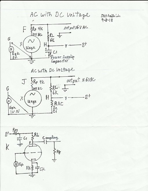
9. So let’s add the DC battery voltage to our Thevenin Equivalent Circuit Figure E? The result is Thevenin Equivalent Circuit Figure F, which deals with both AC and DC voltages.
10. What is the difference between Figure E and F? One difference is power supply filter capacitor C1 is added so our B+ does not short to ground.
11. Secondly, RL is not directly connected to ground anymore at H, but through C1 to ground.
12. So we have a voltage divider, like Figure C, but with an additional part, C1. So we have our AC source, Rp, RL, and C1.
13. Now, we need to understand that C1 has AC resistance (Xc). (Actually reactance but let’s keep it simple with no phase angles.)
14. So now the AC output voltage = 10 x (RL + Xc / RL + Xc + Rp
15. But what value is the AC resistance (Xc)? That depends upon the frequency.
16. (The AC resistance (Xc) is calculated: 1 / 2PI x F x C. That is 1 divided by 6.28 times Frequency in hz times Capacitance in Farads.) As one can see, Xc is frequency dependent.
17. So in our voltage divider, the output voltage will depend upon the frequency since RL + Xc changes with frequency..
18. I have thus proven that the output voltage varies with frequency, thus the frequency response is not flat. (Thevenin Equivalent Circuits have been used in engineering circuits for decades and decades.)
The AC source we used can be simply musical voltage.
19. Figure K is what you would see as the actual schematic circuit that we discussed.
20. If we calculate or measure the AC musical signal current through C1, it will be at least 15 times the musical signal current through the coupling capacitor/Rg combination. I am lenient due to Y (a resistor or choke) siphoning off some AC musical current.
21. We can calculate or measure the AC voltage at C1 but we need to know the frequency. At 20hz, a 20uf capacitor has 400 ohms Xc. The equation is: 6 AC volts x (Xc \ Xc + RL) The answer is approximately 0,2 volts AC. The C1 AC voltage will vary with circuit gain, C1’s value, Rp, RL, AC frequency.
The white paper could go further, because capacitors have ESR, internal inductance, and self resonance problems. Even very small capacitors have problems since tonal balance is so easily perceived.
For such information, please see an article by Walter Jung and Richard Marsh “Picking Capacitors” that includes measurements, resonance problems, ESR, DA etc.
https://www.yumpu.com/xx/document/view/23313452/picking-capacitors-part-1-walt-junghttp://www.reliablecapacitors.com/pickcap.htm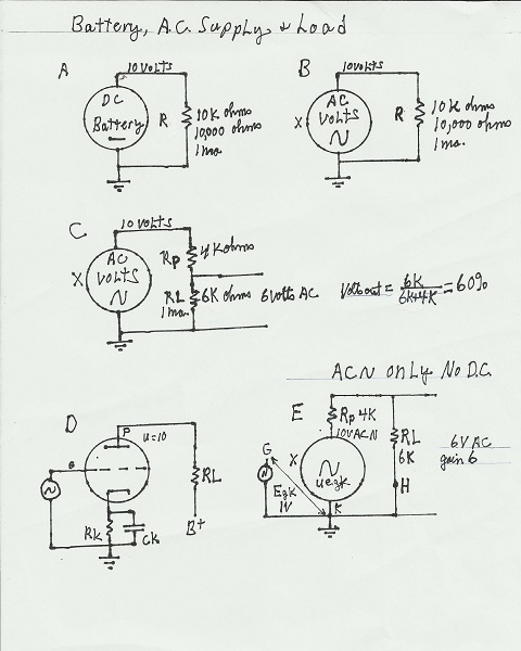
Cheers
steve


