Trimpot / Potentiometer techie issue. Please HELP! Schematic and photo inside...

0 Members and 1 Guest are viewing this topic. Read 3863 times.

undertow

  • Full Member
  • Posts: 925
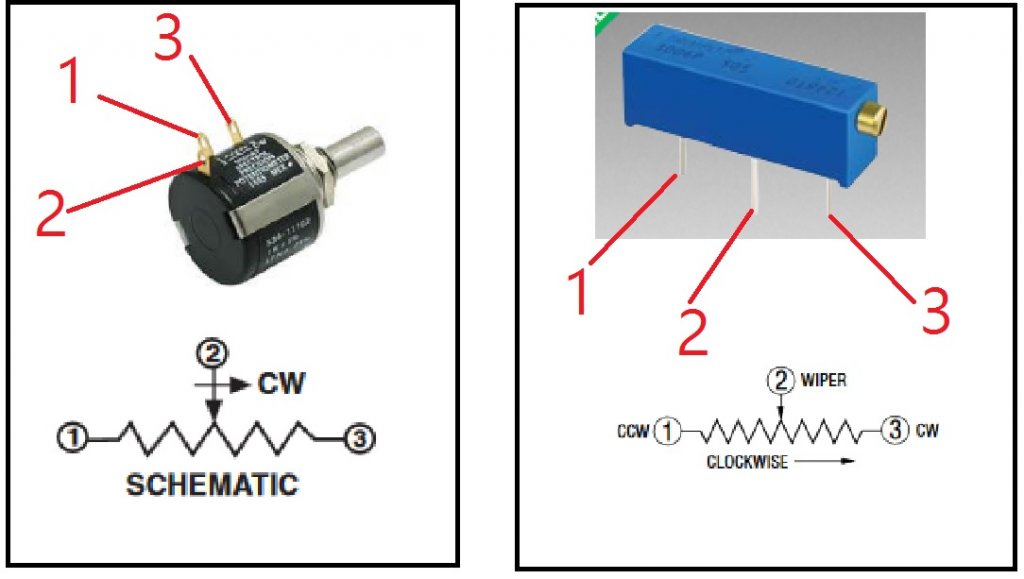
Okay below you will see the physical photo, and pin-out schematic of 2 identical functioning "Precision" trim pots.

Only real difference is obviously the one on the left is a panel mount which can handle 100 times the voltage of the one on the right which is just a simple board mount.

They are both a Multi-turn, both are 1000 ohms, Both are "Linear Taper", both have a standard style 3 pin configuration.

However, because I need to remove the board mount generic trimpot on the Right, and replace with a panel mount version on the left I pulled up the spec. sheet on them both as seen in photo, but as you note the pins are labeled and configured slightly different with the "CW" pin.

The wire, and wiper physical portion of the schematic in the drawing seem to point the same direction? So are pins 1, 2, and 3 all identical on both units and I should just replace the wires to the same points, or do I need to swap one of these to make the new Rotary Pot trimmer work the same function as the surface mount trimpot it is replacing?

Thanks


paul79

  • Industry Participant
  • Posts: 903
What is the trim pot doing? Look at the traces on the one that is in there, and see if 2 of the pins are electrically connected, or if all pins have a separate trace.

However, if you wire the panel mount exactly as the one that is in there, and assuming the one that is in there is exactly the same as the blue one you are showing, and since the pinout is the same with regards to assignment (IE, wiper is pin 2 for both), it will work fine.

Question though, why are you replacing it? So you can adjust externally or some such?

undertow

  • Full Member
  • Posts: 925
Hello,

It is to simply be able to add a standard Knob on the back of a chassis vs having a small screwdriver to adjust. It changes the speed on a turntable motor with a strobe.

As for the pin outs yes essentially they are exactly as you see in photos, and those are the exact units, however the confusion is that the Pin 3 on the surface mount has the CW label, and the Rotary has the CW on the Pin 2. But from the physical schematic it does look as if they both act as the wiper... I believe all 3 traces are isolated on the board.

OH but I do see now they just made it really confusing with the CW label! There is an arrow that is telling that the direction is still to pin 3! It's the same, but they made it graphically stupid. Yeesh... I think I see what happened here.

Thanks
« Last Edit: 17 Dec 2016, 03:13 pm by undertow »

Folsom

The pins are the same, and 1 & 3 can be swapped so you get the turning direction you want for faster or slower, if it's not already.

undertow

  • Full Member
  • Posts: 925
Got it thanks...

Speedskater

  • Full Member
  • Posts: 2733
  • Kevin
The added wires to the panel mounted pot can act as great interference antennas.

undertow

  • Full Member
  • Posts: 925
Speedskater,

I appreciate that. I am going to try to keep a nice tight twist on the wires which are only 24 awg and actually attempt to just even make them longer in order to simply run them way outside on the edges of the chassis around the transformers etc... I was going to go straight back to the pots on back panel, but decided you are correct and these should be completely to the side nowhere near any circuits. Hopefully putting them tight to the side walls of the chassis will lend a little more shielding vs. hanging them free air thru the center of the unit.

I am not concerned about them picking up noise so much as they would not transfer sound back to the motor, but more concerned they would transmit noise out into the phono stage. If this method ultimately proves to cause an issue I will just have to find some shielded thin coax wire?

Actually I have some old Cardas tonearm wire that has Teflon insulation I believe on the 4 lead wires, and the shield could be hooked up as well... I wonder if this is a better bet than twisted pair?

Not sure the voltage ratings on cardas tonearm wiring, but I assume these trim pots don't carry much more than 750 mV or something anyway as that is all those original surface mounts are rated for.