Hello,
I have embarked on the upgrade from RM30 M to the Series II. I have in hand the 10" passive radiators, 10uf caps (original Auricaps to match existing cross over), and I have fabricated the port plugs that will be fitted from the outside. The Mega Woofer upgrade is 10-12 weeks lead time and I will evaluate performance with the original drivers before making the decision to upgrade. I got the CDWG when they were originally introduced.
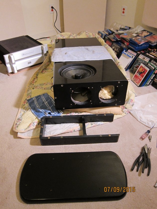
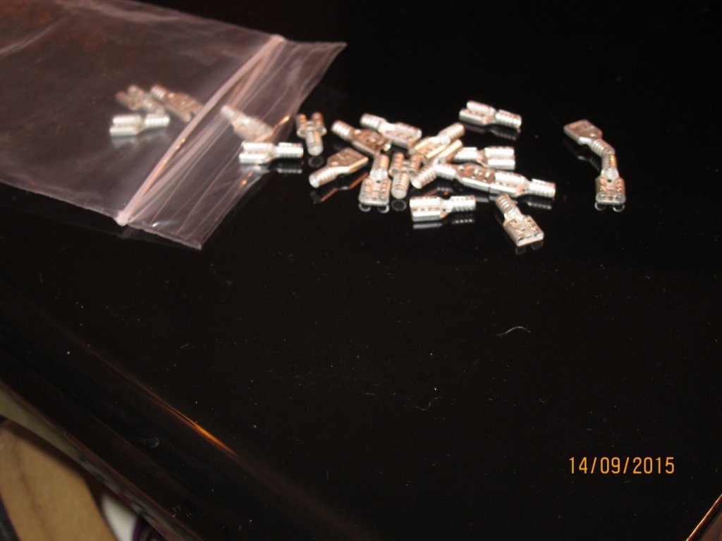
One of my RM30's lays on the floor of my listening room, disemboweled, while I wait for twelve $.10 parts that I need to proceed. These are the female quick disconnects that plug on to the raw speaker terminals. The Misco woofers, both standard 28 oz woofers and 40 oz versions have .205" connectors. The ones you are likely to find in retail establishments are .250" and .187". One could probably use a .250" but I want a snug and proper fit and don't want to revisit this connection once I have it put together. There is only 18 thousandths of an inch difference between the .187 and .205 connector. One might think about "making it fit", but that is how expensive mistakes get started. So I wait and will do it right. Ordered from Mouser some non-insulated ones like Brian used. And some other stuff for other projects in progress.
I added the 10uf capacitor to the midrange cross over. It went smoothly. Lots of light helps and accessing through the bottom PR ports makes it easier as well. I need a better glue gun.
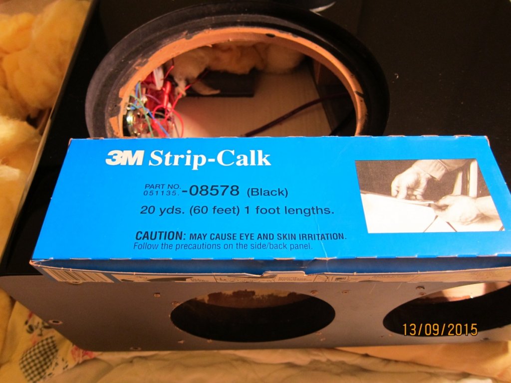
The PR's have a rubber gasket that wrap around the edge and over the top where the screws mount. They give the PR a diameter of 10.25" which doesn't quite fit the cut out. I thought I would need to enlarge the opening but happily the gasket can be removed and it is a perfect fit. The rubber ring doesn't appear to add any functionality except serving as a sealing gasket and making the top of the PR look prettier. I spent some time on the DIY speaker forums and many spoke highly of 3M Strip-Caulk as a sealing gasket. Never dries out and doesn't act like glue. That material also was difficult to source locally, got lucky and found it at NAPA.
I have taken one short cut that may have averted trouble: Rather than unsolder the connections from 10" active to internal speaker post and crossover, I elected to cut the wire from the quick disconnects on the speaker and wrap that exposed wire with two layers of electricians tape. One would need a large solder tip and lots of heat to redo the post/coil connections correctly. I decided to leave it lay.
I have been taking pictures and will document the upgrade process. Hopefully my notes will make it easier for others who take it on.
Update with Pix 9-10-2015
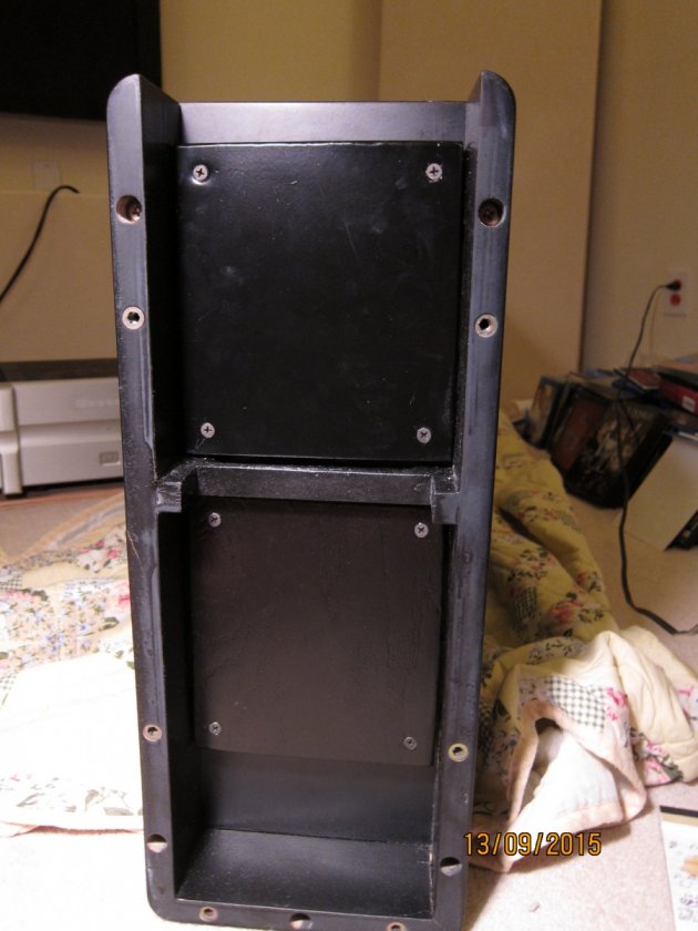
The base is two sections - the frame attaches to the speaker cabinet and the floor section attaches to the frame. 4 screws are covered by floor protectors.
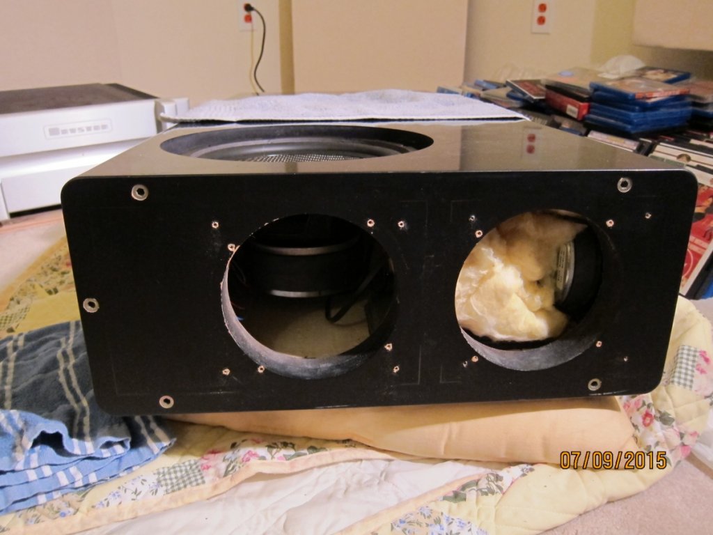
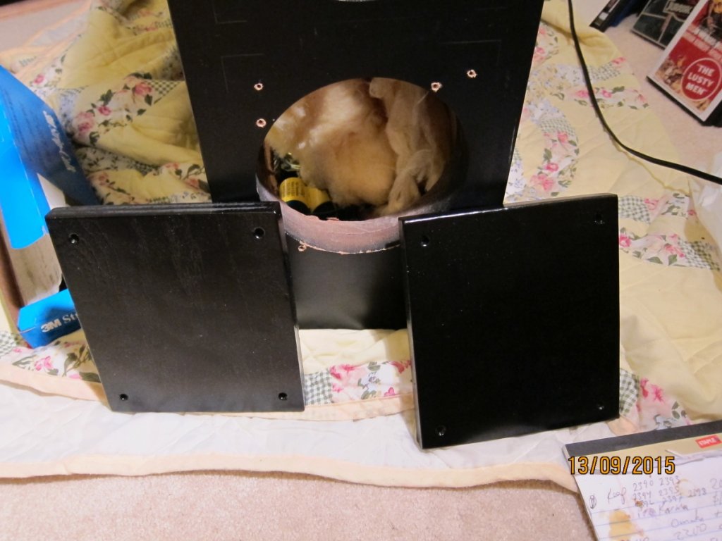
Close up of bottom PR ports. If you look closely you will see pencil marks and additional holes drilled for bottom mounting the PR plugs. I will seal the port plugs using 3M Strip Caulk product.
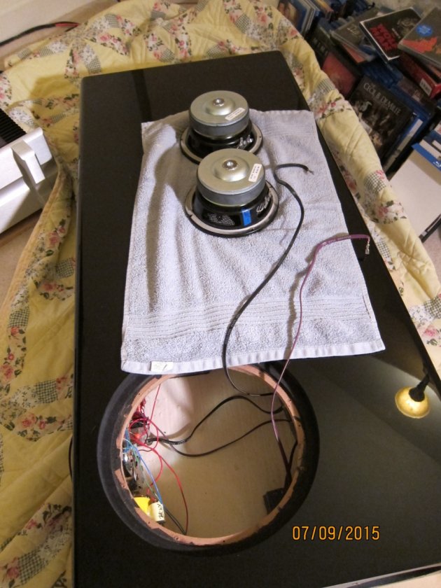
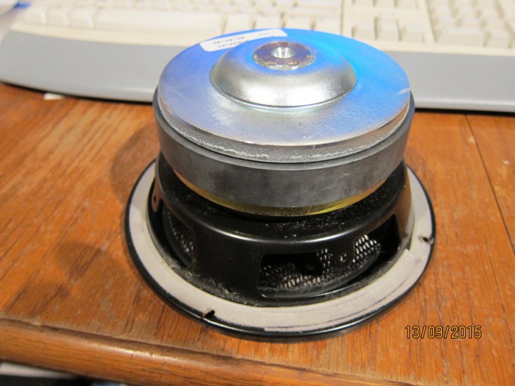
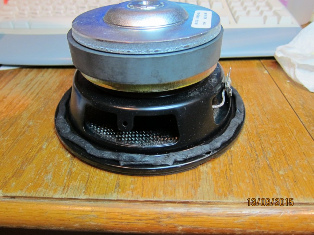
Side firing woofer is out
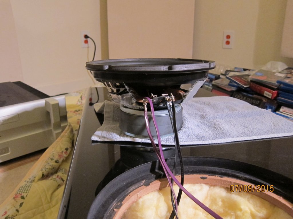
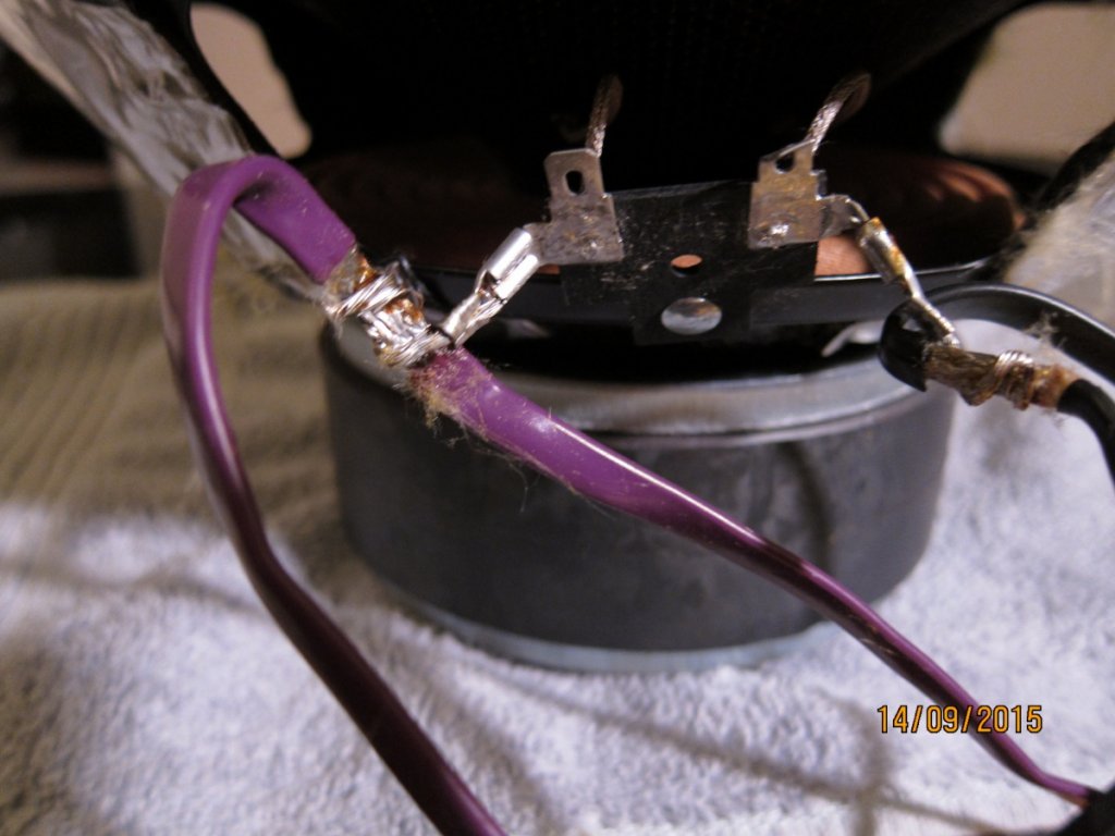
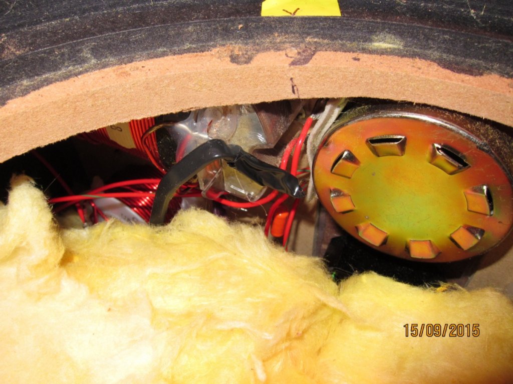
Here is a pic of the internal side of the speaker post and low frequency coils. This is where the wire to the woofers connects. You may be able to see the large cross section of wire and large amount of solder used to attach. I decided to leave it as is.
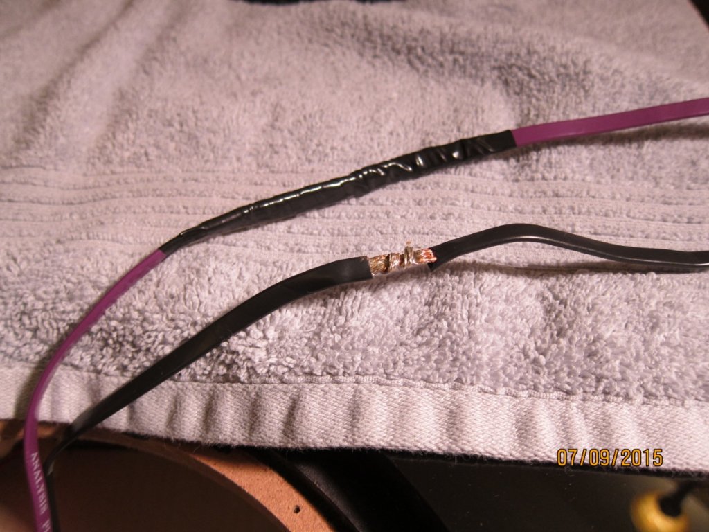
I cut the wire from the quick disconnect for the 10" side firing woofer. One has been wrapped, the other will be shortly. I bent the wire stub the went to the disconnect and used an electricians plier to crimp it down.
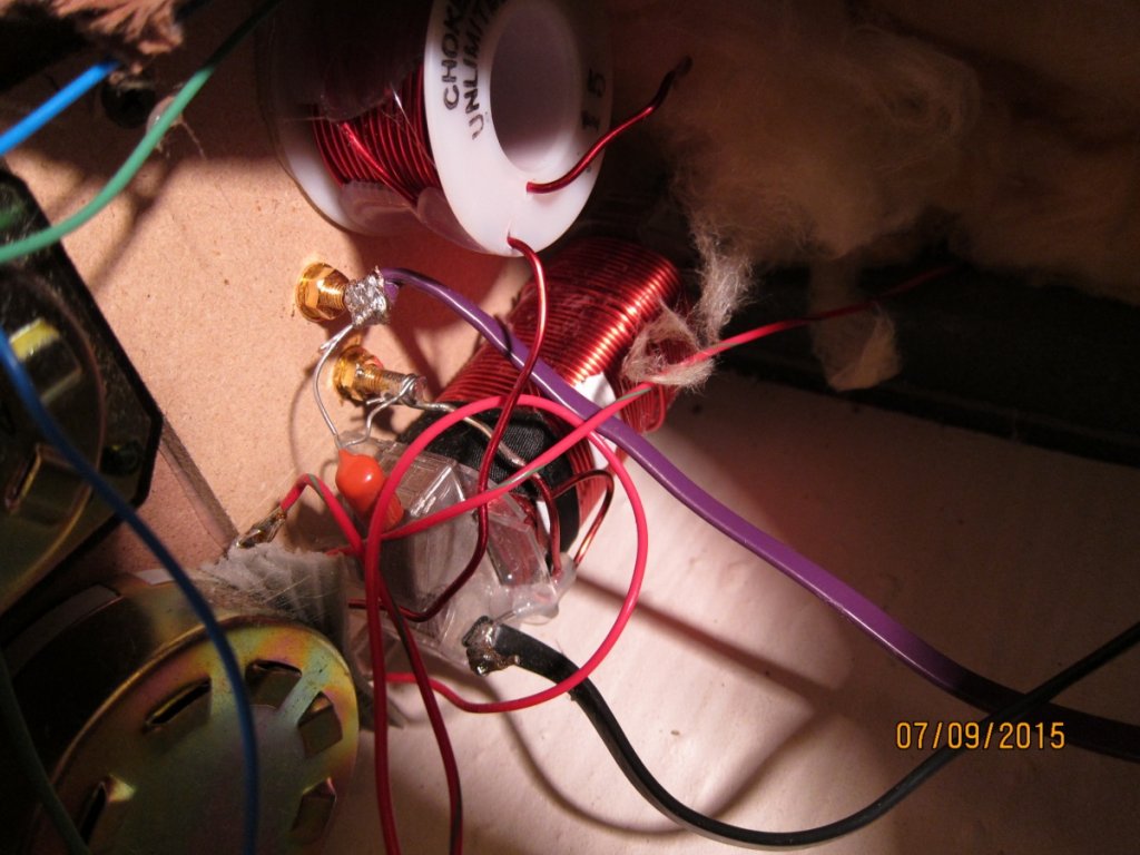
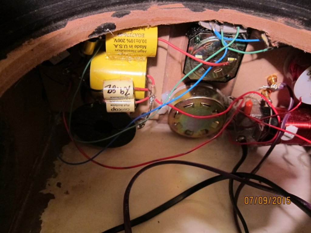
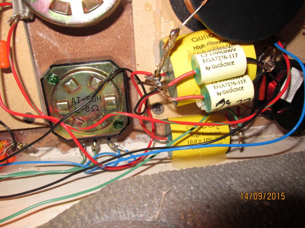
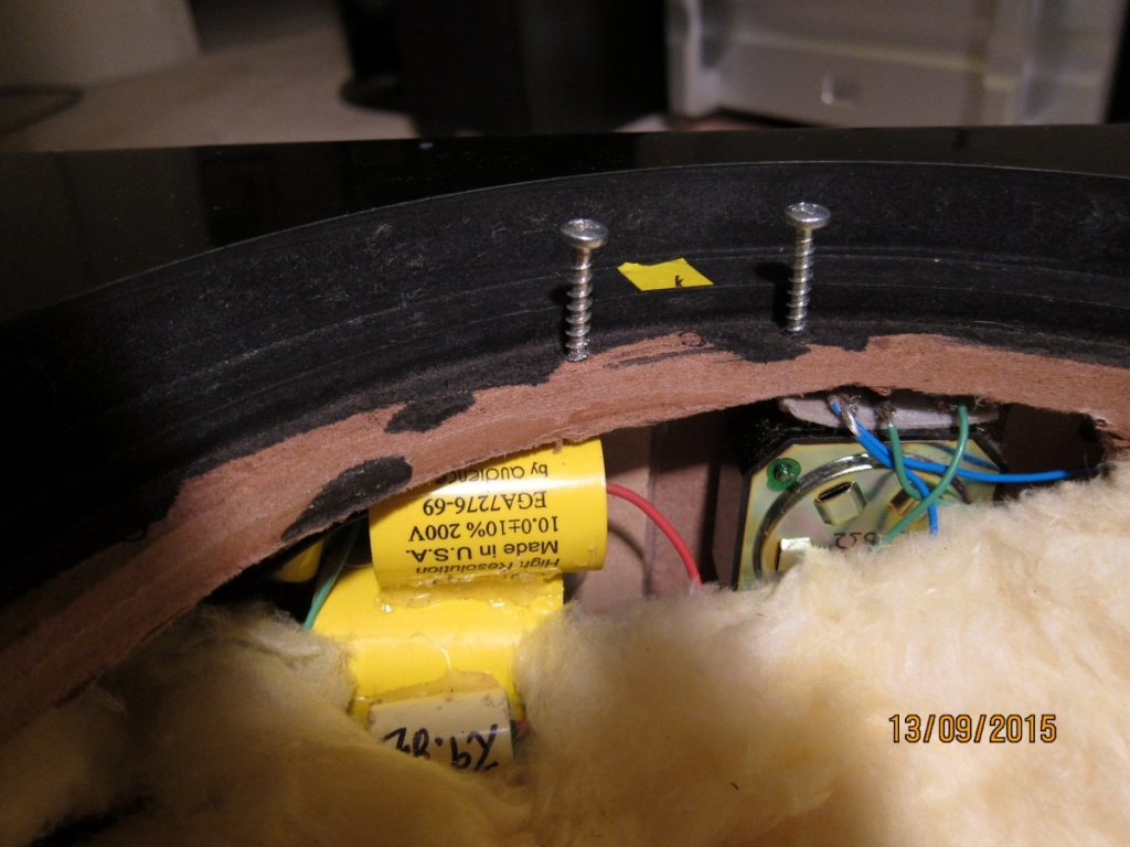
I added my 10uf Auricap to the crossover stack. A neighbor and fellow audiophile will loan me a better glue gun. This is straightforward, match colors on leads, wrap wire on existing leads, use some rosin flux, solder. I stripped off additional insulation to let me get a better wrap. And the pick was taken prior to soldering.
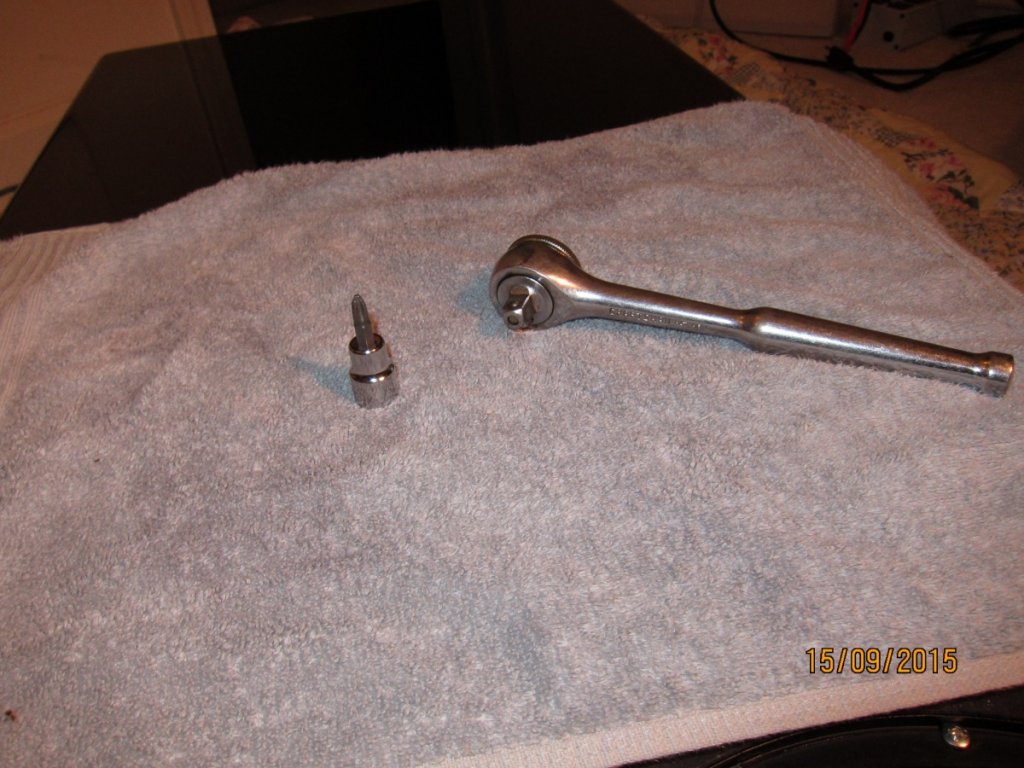
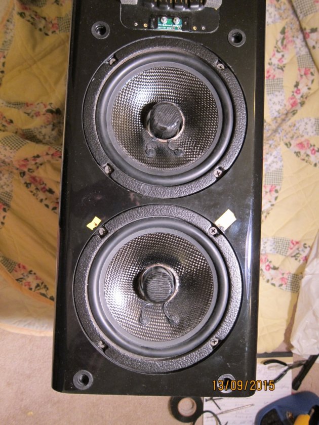
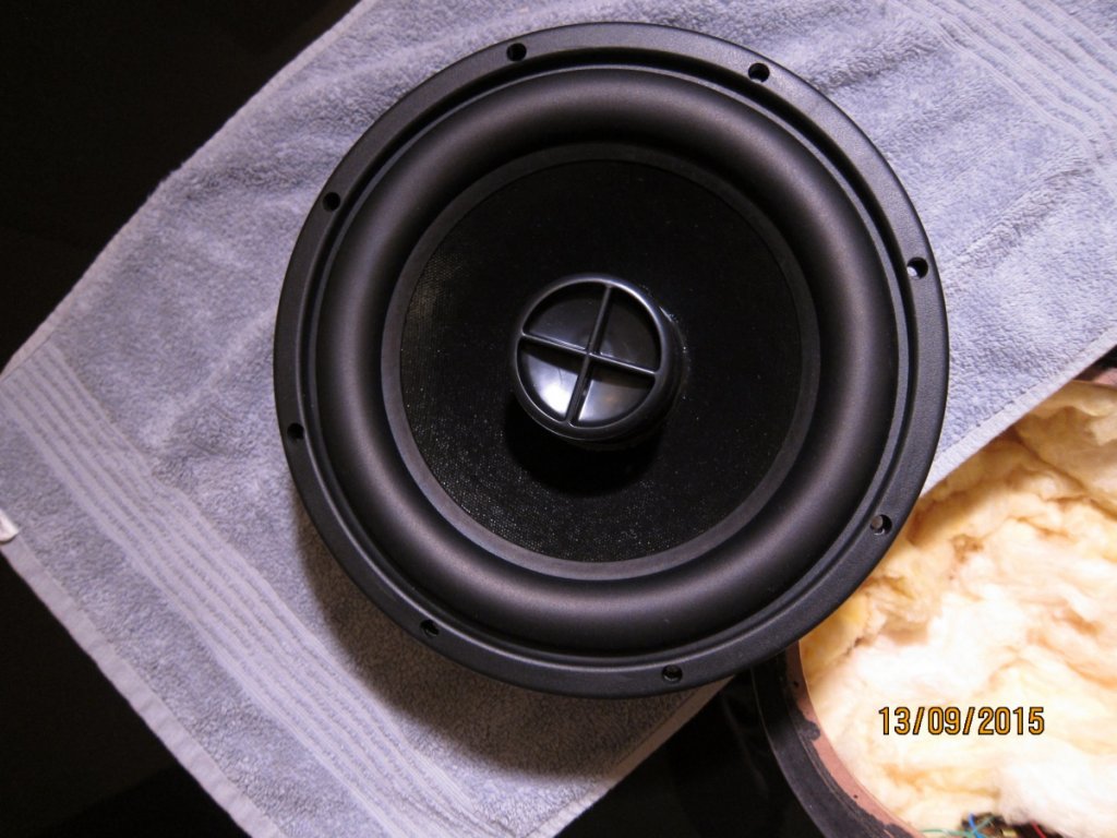
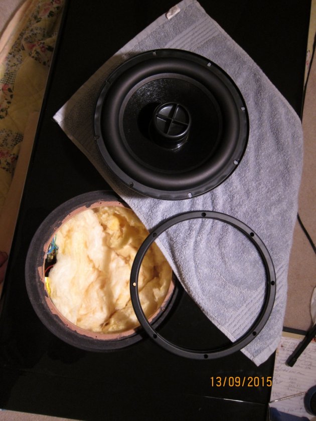
Front woofers out. I was anxious about this step as I know what an errant screw driver can do to a speaker cone. I picked up a phillips driver that is used with a ratchet wrench. It is short and much more easily controlled. Much less drama and a happy outcome! The gaskets sealing these drivers will be replace with the 3M Strip Caulk product.
And now, the rest of the story!OK, my Mouser order arrived and here are the .205” female Quick Disconnects. A perfect fit!
And here is the attachment for my ratchet wrench that aided considerably in the uninstalling and reinstalling of the drivers without mishap!
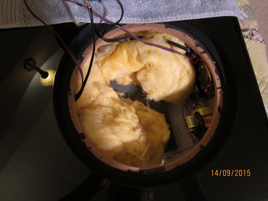
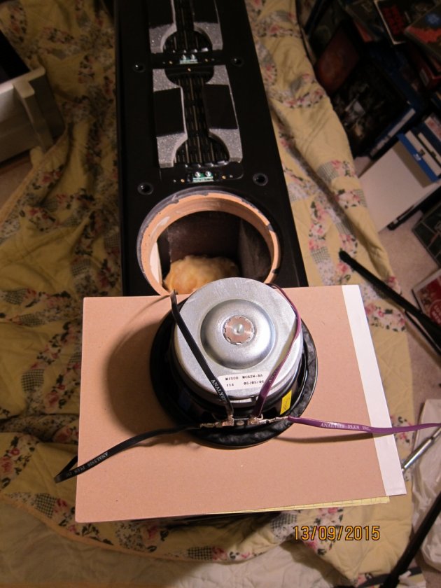
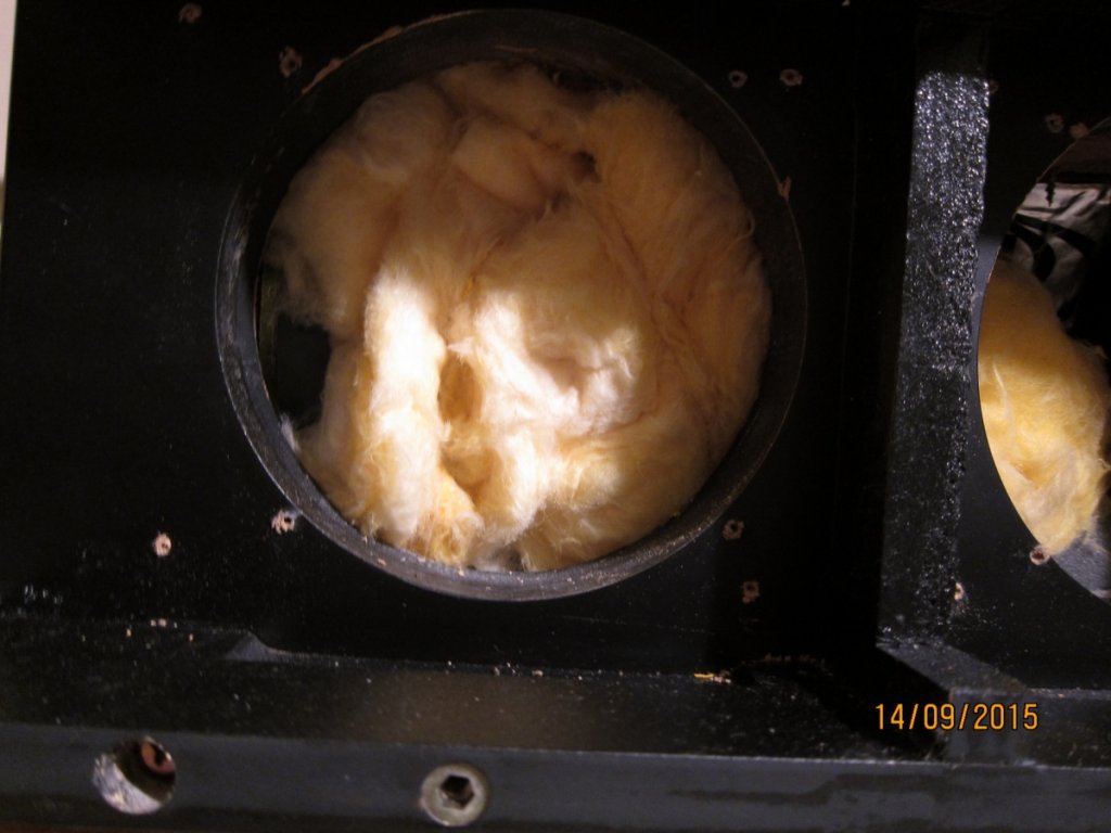
This is the active 10” woofer before I cut off the connections and a pic of the opening. This is for the left speaker, similar to what I showed above for the right speaker.
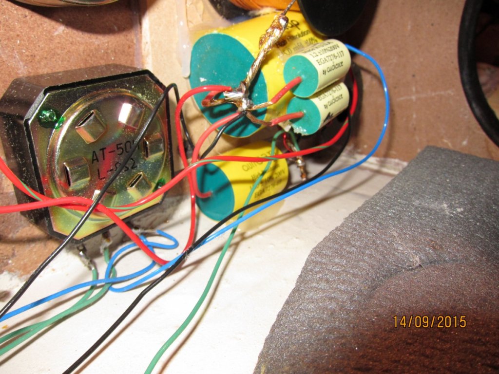
Once all the woofers and PR's are out, remove the insulation and gain access to the crossovers. Here are a couple pix of the mid-range stack after I added the 10uf Auricap to the left speaker. I cleaned up some stray strands from some of the existing wiring. I was careful not to disrupt anything!
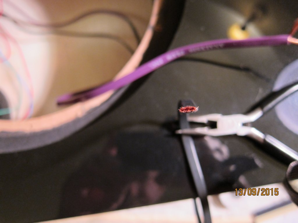
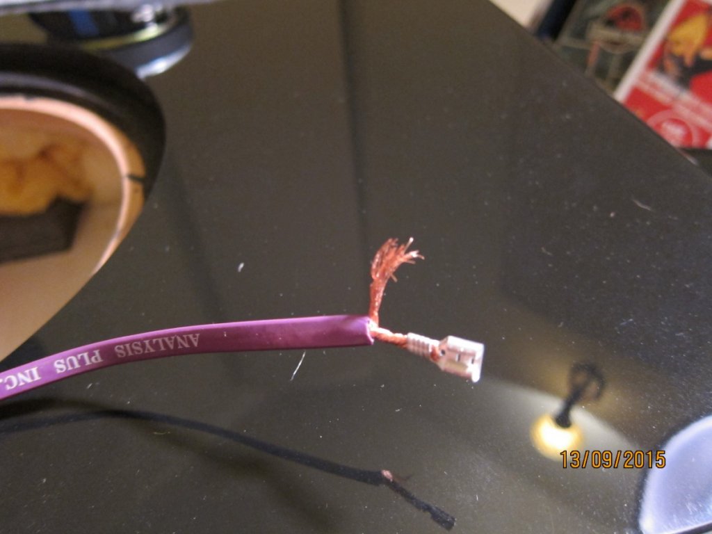
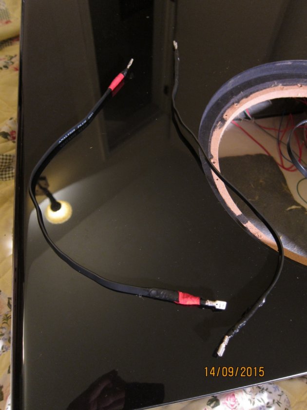
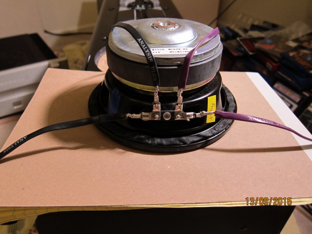
And now we are ready to begin reinstalling woofers and the new PR. Here is a shot of the cross section of the Analysis speaker cable seen as I was prepping for new connectors. It really is oval!
And further prep shots of cables including the jumpers. For the right hand speaker I cut off sections of the wire originally supplying the 10” woofer. I took great care to leave enough so that I could position the 6.5” woofers on the cabinet to make connections. Brian had a single jumper between each pair of woofers because they were serially connected. I now had two jumpers since I made the other pair from material from the the right speaker. All four jumpers are close in length.
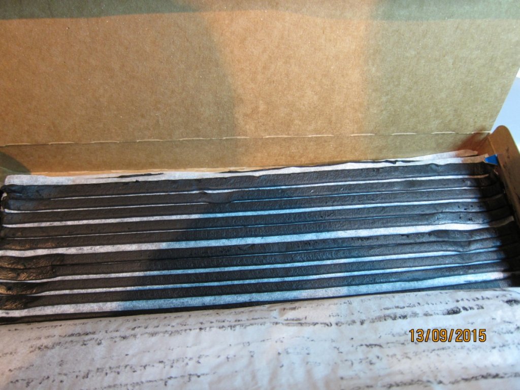
I wanted to have fresh seals for all of the woofers. I decided to use 3M Strip Caulk which is highly recommended on several DIY speaker builder forums. It is sticky as all get out but easy enough to work with. It reminds me of some stuff I used to weather seal my outside satellite TV connections years ago.
Here is the before and after pix of the 6.5” woofers with fresh gasket.
So it comes time to install the 6.5 “ woofers. The pic below shows how I wired them for the right speaker and it fit fine. Just need to be sure the jumpers going to the bottom woofer don't get pinched by the frame.
But for the left speaker, this wiring harness did not fit without pressing the terminals so far back and away from the hole edge that I was concerned with shorting to the speaker frame. I guess the cabinets were constructed slightly differently.
So I had to go an alternate route. I had to refab the connections:
For the wires supplying the upper woofer – I cut off the quick disconnect terminals and prepped the cable similar as I had previously. I then cut off the quick disconnects from one end of a jumper and prepped it. So each cable had two groups of strands.
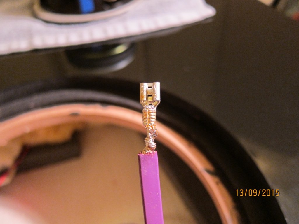
I tightly twisted together a strand group from a supply line and a jumper and checked the combined strands fit the barrel of the quick disconnect. Rosin flux was applied and soldered it to the quick disconnect.
The remaining strands were tightly wrapped around the exposed wire coming out the bottom of the quick disconnect and soldered. I then wrapped these exposed wires with electricians tape. I extended the tape a couple inches down the insulation to make sure they could not be pulled apart. This needs to be done for the “+” and “-” terminals.
So for my left hand speaker, instead of quick disconnects on all four upper woofer terminals, I only have connections to the terminals pointing downward, with the soldered jumpers going to the bottom woofer.
I regrettably did not take pictures of this although I intended to. I may do a mock up and photograph that and add it to the story. But again, my other cabinet did not present this issue.
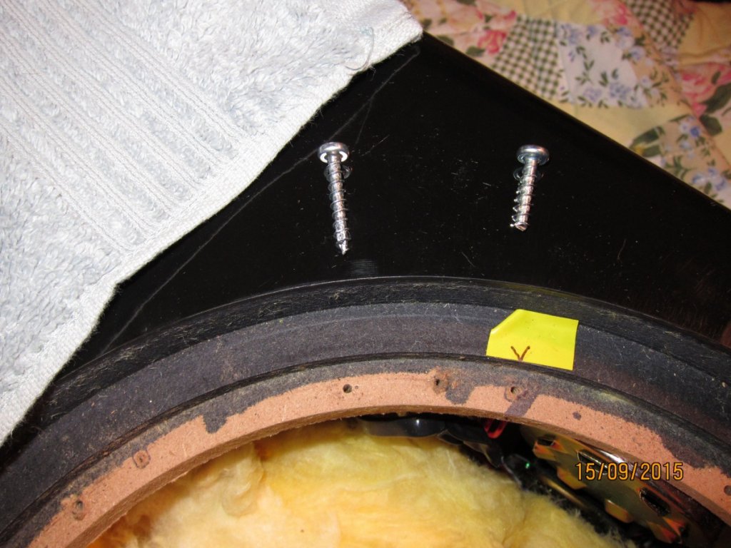
The caulk strips I added to the speaker frame blocks the mounting hole. In order to align these with the mounting holes in the cabinet, I used yellow tape with a line pointing to the hole. I did this for two holes each speaker. I used fresh 1-1/4” coarse thread dry wall screws like Brian had in original construction.
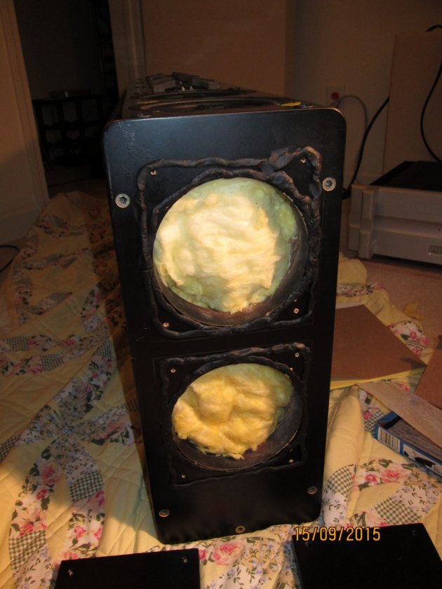
I then re-stuffed the insulation.
Now, on to the installation of the new PR!
The PR's come with a rubber ring gasket that not only seals the bottom of the PR frame with the cabinet, but also wraps around the edge and top providing a finished look. Unfortunately this means it won't fit the cut out, at least in my version of the cabinet. This rubber ring easily comes off and it then fits perfectly
Before installing the PR's I needed to check screw clearance with the added capacitors and other elements of the cross over. Both right and left speakers presented challenges:
I used the rubber ring to help me determine best new hole alignment. I marked the critical placement by the crossover components and then used the PR itself as a template to mark the new screw placement. I then drilled small pilot holes at these locations.
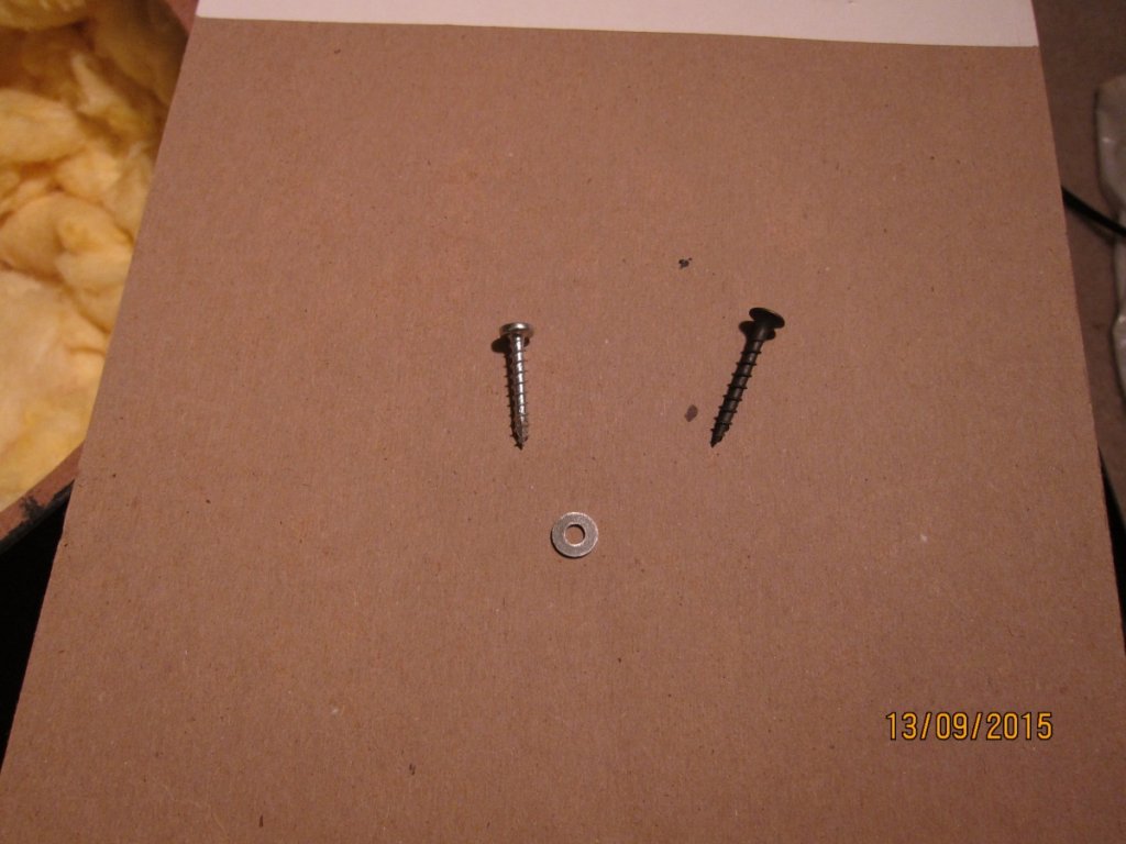
Rather than use the coarse thread drywall screws like I did for the woofers, I decided to use 1” constructions screws with Pan style head – these are flat bottom screw heads. I had planned to use these with washers but they were too large to fit inside the frame of the PR.
For the left speaker I needed to cut one screw short - the one that is quite close to one of the coils and pot. It only needs to be slightly longer than the material it screws into.
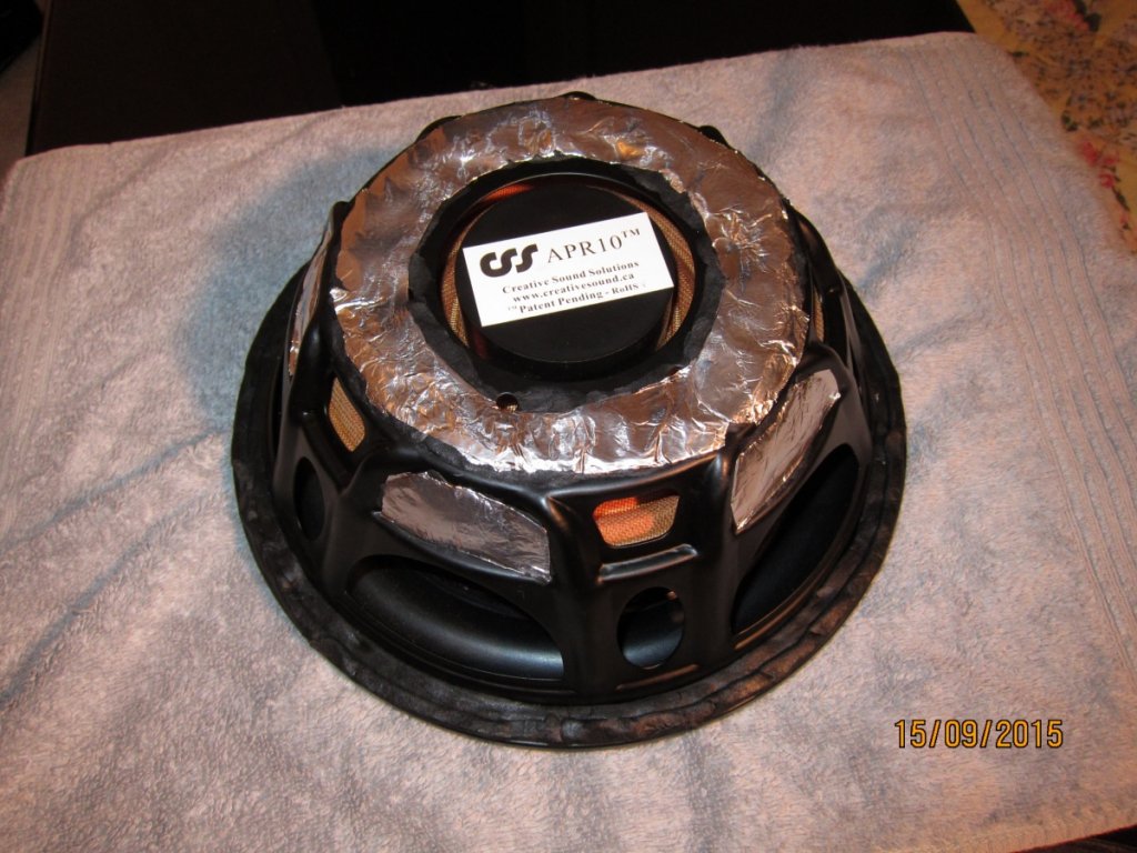
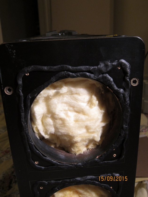
Before I installed the PR, I had tapped the frame and heard a distinct ring. So I used some 3M strip Caulk and treated the frame to tame resonance. I covered the goo with heavy duty aluminum foil so insulation wouldn't get stuck all over it.
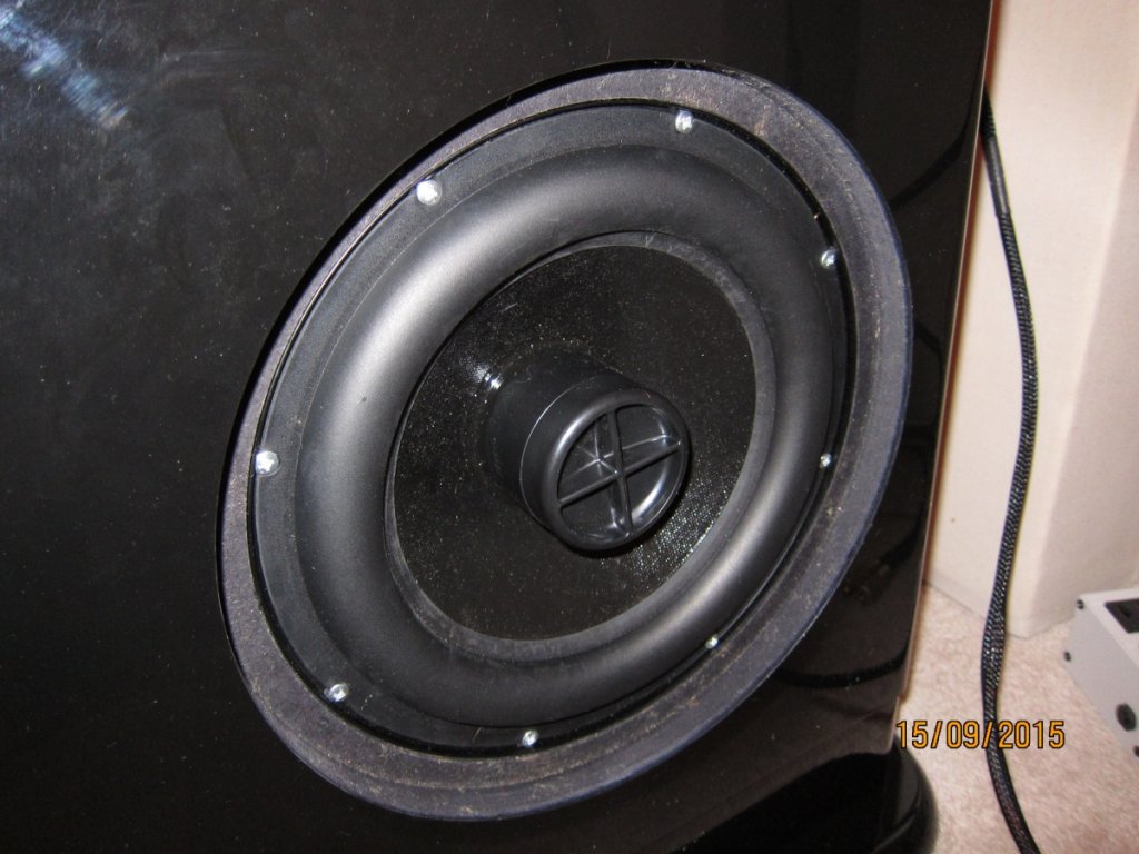
And here it is installed
Time to install the bottom PR plugs. I made these out of ¾ inch plywood and painted them black to match my cabinets. Before I removed the base of the cabinets I used a pencil to outline the inside of the frame. I also measured the dimensions of this interior space. I drilled holes in each corner of the square plug and then corresponding pilot holes in the cabinet bottom. BTW, the holes in the plug should be large enough to let the screw pass through unimpeded. THE PILOT HOLES NEED TO BE SIZED APPROPRIATELY FOR THE SCREW YOU WILL USE. You can always drill the pilot holes bigger, it's lots more work if you drill them too large. I used 1-5/8” coarse thread drywall screws.
I used more of the 3M Strip Caulk product to achieve an airtight connection. One probably doesn't need to use quite this much.
And here are the port plugs installed. I used a screw driver to get the plugs in place and then I installed the frame of the base to make sure clearances were OK. Then I removed the frame base and used a phillips driver in my drill to drive the screws home.
And it is finally done.
This is an involved project – if you decide to pursue it, you now have an inkling of what you are getting into.
I have only listened to a couple elpee sides but the low end is definitely enhanced. And the glorious mid range remains intact.


