Over the past month we've been evaluating the first prototype of the V3 version of our LDR preamp controller design. As a result, we've made some significant changes as outlined and shown below.
The biggest change is the integration of input switching into a now headless (no microcontroller) LDR board (formerly called a slave board). We are convinced that integrating the input switching and thus minimizing the input/output wiring and connection points can only help to improve sound quality.
As with our V2.1 boards, the V3 will have fully integrated autocalibration of the LDRs.
All control has been moved to a single controller board (not shown, formerly called the master board) which mates up directly (or via ribbon cable) to a single graphical OLED (LCD) display module.
One very interesting option that we are continuing to explore is to adopt the Raspberry Pi computer (
https://www.raspberrypi.org/help/faqs/Pi) as our core controller in lieu of a microcontroller. For those who've never heard of it, the Raspberry Pi ("RPi") is a $35 Linux computer on a single board the size of a deck of cards. Although it has far more processing power than needed to run our LDR preamps, the RPi is quickly evolving into a feature rich embedded processing device that can make the "internet of things" ("IoT") a reality far sooner than anyone expected. Initially released in 2012, the current version of the RPi has it all - USB, Bluetooth, WiFi, HDMI, video, audio, and significant memory/storage capacity - plus tons of development tools, video display drivers etc, much of which is open source. To be clear, we are NOT proposing to use any aspect of the RPi's audio features, simple it's processing, control and communications abilities.
Even if we don't use the Raspberry Pi for the V3 version of our preamp controller, we might do so later on. Equipped with a proper adapter board, the RPi would be fully compatible with the LDR Board shown board.
Last but not least, the release of the V3 remains at least 6-9 months away and that's probably optimistic.
* The controller board (now shown here):
* Handles all control processing of the LDR board(s)
* Connects via ribbon cables to up to 6 stereo LDR boards (12 total channels)
* Interfaces directly with an OLED display panel to which it can mount to directly
* Handles encoder input
* Handles firmware updating via USB connection
* Handles IR remote input
* Handles Bluetooth remote input
* Uses a single 80 pin 8 bit surface mount microcontroller
* All electronic components are surface mount
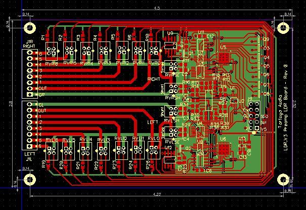
* Each LDR board (shown below):
* Handles a single stereo single ended input (2 channels)
* Connects to the controller board via 10 pin ribbon cable
* Is powered by the controller board but has its own voltage regulators separate from the controller
* Has no digital microcontroller of its own
* Can accommodate from 1 up to 6 inputs without an external input relay board
* Input expansion is handled by plugging in additional LDR modules
* All input switching done via plug in LDR modules (no relays)
* Utilizes 5 12-bit DACs, 2 12-bit ADCs, and 3 op amps for far more precise and flexible control of the LDRs compared to the V2 board
* All communications between the controller board and LDR board is handled via a 4 wire SPI serial data link.
* All electronic components except for LDRs are surface mount
* Measures 2.8 x 4.5 inch