Hi all! My name is Jan and I live in the Netherlands.
I'm a music lover and home theater fanatic for more than 25 years. Approximately 5 years ago I started building my own dedicated listening room in my backyard (a project which I call(ed): ‘Confidence Mansion’). I finished this dedicated listening room project in May 2012, but the real cherry on this project was (of course) my recent purchase of a Von Schweikert VR10-MK-II system in the end of May 2013 (a system of which I, until recently, could only dream).
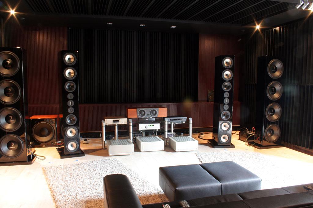
The picture below shows the first initial set-up of the system based on room acoustics simulations and predicted frequency response characteristics of the VR10-system. I’m currently in the middle of my (new) journey of further optimizing the performance of my audio system. As I’m relatively new here on the forum, I will first introduce my gear and situation in this posting (starting with a ‘how it is made’).
I will keep you updated and if you have any questions, comments and/or suggestions, please let me know!
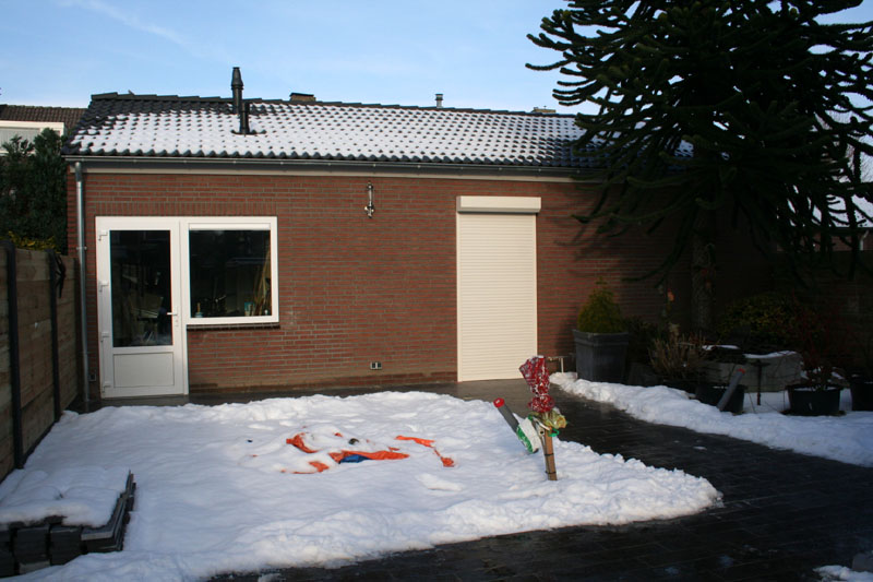
 The starting point for Confidence Mansion
My starting point for the dedicated listening room (also to be used as Home Theater) was optimizing the audiophile properties of such a room with a minimum of concessions regarding these aspects (thus in principle go always for the ‘full 100%’ unless there are very good reasons (e.g. money / effort) to deviate from this starting point. The main reason is that in my current situation the ratio between music listening versus watching movies is about 80:20. This doesn’t mean that I cut down the budget on audio-visual means such as the projector and the projection screen, but taking into account all the expenses in relation to this listening room such expenses could shift to a later time-slot (note: I’m not a millionaire). While making the planning for this listening room all the aspects (e.g. music listening / movie watching / looks / comfort / …) were taken into account parallel already from the start of the built (so first fully consider everything from A until Z including all the consequences relating to it and only after that really start with the execution of A). The final ‘looks’ of this dedicated room were of course also important, but came for me on a second place. When I had to make a decision relating to the acoustical properties of this listening room versus the looks of it, the first property was in almost all cases decisive (if I listen to music I will use my ears and not my eyes and the light is off when I watch a movie). This didn’t give me however a wildcard to create a very freaky room. Forces from outside (i.e., my girlfriend) compelled me also to take into account such aspects of this listening room. She wanted for instance luxurious chairs or a big couch on which she can sit in a very relaxed way instead of e.g. the well-known (but not so comfortable) small red cinema chairs (otherwise: “She would refuse to join me while watching a movie”). So the first concessions already needed to be made before even starting, although these aspects weren’t on beforehand in contradiction with each other (but you have to consider everything into detail). The colors that I used are also a compromise, e.g. black is too black and red is too common (but as you can see on the pictures, also here we came to a good solution/compromise). In summary: this listening room strives for a maximum of audiophile properties for both music listening and watching movies, the visual equipment in the room is also optimized and the esthetic aspects are (as far as necessary) taken into account, but were never decisive if this had negative consequences for the audiophile properties of the room. The name for this listening room was decided to become: ‘Confidence Mansion’. My initial and ‘ultimate goal’ was to build up a complete Home Theater setup using Dynaudio speakers from the Confidence-series. Meaning: Dynaudio Confidence C4’s as front speakers in combination with a Dynaudio Confidence Center and Dynaudio Confidence C1’s as rear speakers (maybe including an extra pair of the latter speakers) and including at least one Velodyne DD-18 subwoofer. How things can change however becomes clear from the title of this topic. Earlier this year I became aware that the previous owner of this system wanted to sell his system to become audio-equipment dealer for another brand and for which he needed all the space he had (including the listening room where he placed this Von Schweikert system). Lucky me! The confidence I had 5 years ago to start this project anyhow despite the dark economic clouds hanging over the Netherlands (and still hanging there) decided me to keep the name as it is (at least for now).
In the overview below and for everyone who is interested, I wrote down some considerations and decisions that were made while designing and building ‘Confidence Mansion’ with respect to:
- Acoustics;
Mechanical aspects of the building;
Power supply;
Choice of the electrical power cables;
Separate audio-groups;
Fuse boxes and fuses;
Wall sockets;
Comfort in the dedicated room.
The basis: AcousticsBeing familiar with the phenomenon: ‘listening room with problem frequencies’, this project started by making the decision to build a complete new listening room with a minimum and preferably no problem frequencies. My girlfriend encouraged me to do so, as in my previous situation our living room was for a big part dominated by the Home Theater set-up especially when the Confidence C4’s arrived. This meant however check what is allowable by the local authorities, start with acoustic simulations, go to the blackboard and start building after that your complete garden is empty (including cutting down trees and demolishing previous buildings). After discussions with the local authorities it became clear what the maximum surface and height of the building could be and acoustic simulations started to determine ideal ratios. In my situation a maximum surface of 810 square feet and a maximum height of 14.8 feet were allowed by the local authorities. After knowing these values an iterative process started to find the most ideal ratios for the listening room while also taking into account other wishes and requirements. As a consequence of creating so much space in my backyard and creating an opportunity to completely redecorate the garden also my former garage and shed needed to be demolished and therefore also a part of the 810 square feet should also be suitable as a new shed. It was however also decided not to rebuild the garage, so I sold my Pontiac Fiero GT from 1988 (which I owned for almost 12 years). Within the maximum boundaries available for this listening room length x width x height being (26.3 x 21.3 x 10.5 feet) it appeared that internal dimensions of 24.38 x 19.23 x 9.09 feet would be ideal (meaning approximately 4240 cubic feet effective listening room). The outside dimensions of the complete new building became eventually 35.4 x 21.4 x 14.8 feet (meaning 9360 cubic feet capacity) including a significant space under the roof of this new building (e.g., to story all the audio equipment cases and boxes).

Based on these dimensions I contacted an architect to formalize the plans into actual drawings which still needed to be accepted by the local authorities (which succeeded after one iteration => initially they did not like the proposed angle of the roof). Already in this stage of the project it was necessary to take into account the final finishing of the listening room. It was e.g. decided that the walls would be plastered and therefore the internal dimensions between the walls of the structural work were increased slightly to allow a certain thickness of the plasterwork. Also at this point it was decided that a wooden floor would become the finishing touch on the ground and therefore the internal ceiling height was increased by the thickness of the wooden floor. In this case it was decided to use a wooden floor and not for instance laminate or carpet, because the laminate would probably result in a very frequency specific damping and the carpet would probably result in an over-damped listening room (in both situations it is easier to add specific damping than to remove specific damping). To control the broadband reverberation time in the listening room a total of 7 Helmholtz-resonators were designed and build, each with their own specific volume and effective frequency. The frequencies of these Helmholz-resonators are tuned at 46, 50, 63, 71.5, 80, 100 and 122 Hertz (having a total volume of more than 400 cubic feet!). After completing the building of these resonators an actual RT-60 measurement was done to verify and to confirm (lucky me!) that the simulations appeared to be correct. Damping in the listening room above these frequencies is mainly realized by a plastered ceiling that is placed approximately 7.9 inch below the concrete ceiling and which is furthermore filled with acoustic damping material.
It is furthermore realized and taken into account that symmetry is very important in a listening room. The only asymmetry is caused by the inevitable entrance of the door, but this asymmetry is solved by applying sliding diffusion panels. These panels are slidable for the entrance door when listening to music or watching a movie. Furthermore diffusion panels are added on all first reflection points of the front and rear speakers on all the walls (front wall, side walls and back wall) and also on the ceiling. On the sidewalls near the front speakers so-called RPG diffractals are placed as they have a superior diffusion frequency behavior compared with the other diffusion panels. It should be noted that the in total 64 diffusion panels and the 16 RPG diffractals also have a damping effect that also should be taken into account!
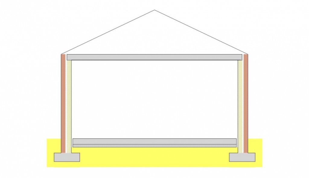
Mechanical aspects of the buildingWhat applies for audio equipment and e.g. audio racks also holds for the building itself. Direct and indirect vibrations that are caused by driving the speakers and subwoofers are preferably not transferred via the floor, walls and ceiling to the other parts of the building and parts inside the listening room that could start resonating. To minimize the excitation of such kind of resonances, special construction measures are applied as discussed below.
First of all, the floor in the listening room on which the speakers and subwoofer towers are placed is substantially dynamically decoupled from the rest of the building. The floor is a directly, by cast concrete, formed free floating plate with a thickness of approximately 7.9 inches and an estimated weight of around 44000 pounds, being spring supported by a thick layer of polystyrene foam that is supported on the fixed world, preventing that vibrations that occur in the floor reach the rest of the building. Furthermore all inner and outer walls in the building are formed by thick and heavy bricks with in between a large cavity that is partly filled with acoustic insulating material, forming a total wall thickness of 12.6 inches whereby there is no direct mechanical connection between the inner wall and the outer wall. Finally, the ceiling of the listening room comprises 4 prefabricated floor parts, which are mutually connected with iron reinforcement material and flooded with cast concrete, consequently forming one massive and very heavy plate. The total thickness of this plate is approximately 8.7 inches having a total weight of around 48500 pounds (in fact the whole listening room is built as a room inside another room and only shares the foundation with the outside wall). All these measures serve the purpose to prevent that the listening room or parts located inside the listening room start to resonate due to vibrations originating from vibration sources inside the room. A second aspect of this mechanical construction is that it also forms a very effective mechanical filter for vibrations that originate from outside the listening room (both for vibrations via the ground, but also via acoustical excitation). A similar construction, but than in an even more extreme embodiment, is present in a special reverberation room at the Philips (NatLab) physical laboratories (located in Waalre, the Netherlands) that is fully acoustically and vibriationally isolated and in which very accurate sound power measurements can be performed (I should know, because I worked there for a few years). Finally the entrance of the listening room is provided with a special selected door, including special glass to make it as sound proof as possible.
 Power supply
At the start of this project some modifications were made to my original power supply to enable the usage of the already available, but not connected, 3 phase power supply being present between the street and the distribution cabinet in my house (meaning e.g. a new power meter, two additional and extra heavy fuses, et cetera). After rebuilding the complete distribution cabinet in my house, the ‘new’ 3 phase power supply was extended to the separate building in my garden to end up in a second (‘3-phase’) distribution cabinet located in the shed. At that location it is measured which of the three phases shows the minimal amount of distortion and that phase is further extended to the dedicated room and only used for the power supply of the, in total eight, audio groups. The remaining two phases are used for e.g. lighting and the other power consumers in the building. The second phase is, as a rule of thumb, mainly used for my home and all lighting in the separate building (including that in the dedicated room) and the various wall sockets and the third phase is used for the (potential) big power consumers such as a dedicated air circulation plant, the central heating boiler and optionally an air conditioner which seems not to be necessary as currently in ‘my part’ of the Netherlands the temperature is about 91 degrees Fahrenheit, which is pretty extreme, and the temperature inside the listening room remains constant about 70 degrees Fahrenheit.
 Choice of the electric power cables
Between the distribution cabinet in my home and the distribution cabinet in the separate building use is made of a 5 x 0.056 square inch (~6mm2) Draka Vulta Mb power cable which is unshielded. Between the distribution cabinet in the shed of the separate building and the distribution cabinet in the dedicated room use is made of 3 x 0.056 square inch Draka Vulta Mb. From the latter distribution cabinet 3 x 0.056 square inch Draka Vulta Mb is used to supply the CEE wall sockets and 3 x 0.025 square inch to supply the HMS wall sockets. The CEE and HMS wall sockets can be used to provide power to my audio equipment. The reason why unshielded power cable is used relates to the presence of undesired capacitive effects of such a shielding. Furthermore it is assumed that power cables are mainly the course of crosstalk, so there where no signal carriers are in the neighborhood, it seems not to be meaningful to use shielded power cables. Taking into account that the whole power supply of the dedicated room is set-up spaciously both with respect to volume as power capacity it is possible to locate all power supplying cables far from each other to realize space for all the signal carriers. Furthermore the whole power supply in the dedicated room is, as good as possible, shielded by using a so-called ‘Cage of Faraday’ that is connected to a separate earth contact. At those locations where it becomes impossible to separate power supplying cables and signal carriers (from a practical point of view ‘after’ the wall sockets) well shielded power cables are used to prevent possible crosstalk problems. Incorporating this whole layout of the power supply at the start of this project enabled the realization of this principle idea. The separate earth contact is made of massive copper rods which are mutually connected up to a total length of 30 feet. This earth contact is mounted into the ground directly nearby the power cabinet in the dedicated room.
Separate audio groupsIn this dedicated room there are in total 8 separate audio groups available:
Group 1. Amplifiers (left) (maximum 4 pieces) using CEE-form;
Group 2. Amplifiers (right) (maximum 4 pieces) using CEE-form;
Group 3. Amplifiers (left) (maximum 4 pieces) using HMS wall sockets;
Group 4. Amplifiers (right) (maximum 4 pieces) using HMS wall sockets;
Group 5. Subwoofers (maximum 2 pieces) using HMS wall sockets;
Group 6. Analogue sources using HMS wall sockets;
Group 7. Digital sources using HMS wall sockets;
Group 8. Projector directly coupled to the power cabinet.
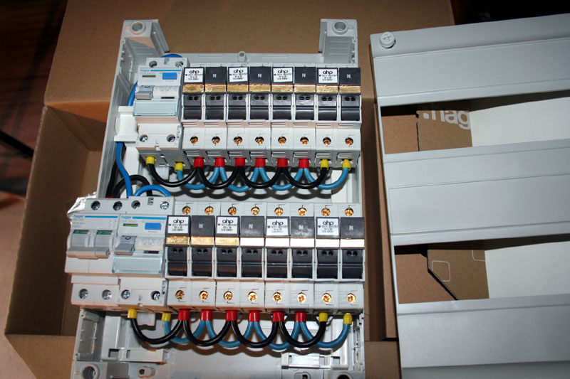
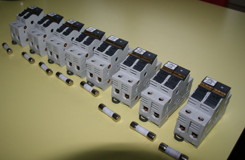
Fuse boxes and fusesAll eight above mentioned audio groups comprise a ‘HMS Klangmodule 3i’ fuse box including a specially designed so-called ‘flat wire fuse’. Although in the current design of the dedicated room it is always relatively easy to approach these fuse boxes, but maintenance of the fuse boxes is undesired (i.e. ‘polishing the fuses’), it was decided to choose for HMS fuse boxes instead of e.g., alternative Siemens fuse boxes, although the latter fuse boxes are approximately 50% cheaper.
 Wall sockets
The CEE-form wall sockets are wired with 3 x 0.056 square inch (~ 3x6mm2) Draka Vulta MB meaning that these CEE-form audio groups are fully wired with 0.056 square inch electric wires. The HMS wall sockets (type ‘gold-plated’) are electrically wired with 3 x 0.025 square inch (~3x4mm2) simply because there are no audiophile wall sockets (at least as far as I know) suitable for larger diameters of electrical wiring.
...end part I...


