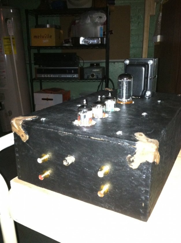
Here is my aesthetic take on the Cornet. I used a vintage, wood LP box, cut off the bottom 1/3 of the bottom, flipped it over and painted it black to make a Cornet2 type chassis!
Greetings! Longtime lurker and first time poster.
I obtained what I thought was a Cornet pcb from a friend and proceeded to order all of the parts for the Cornet kit. My friend did most of the pcb assembly including the resistors and caps. I soldered on a few tube sockets, connected the RCAs, and transformer.
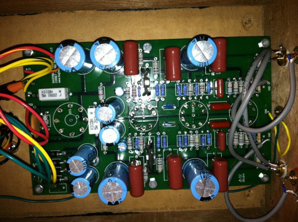
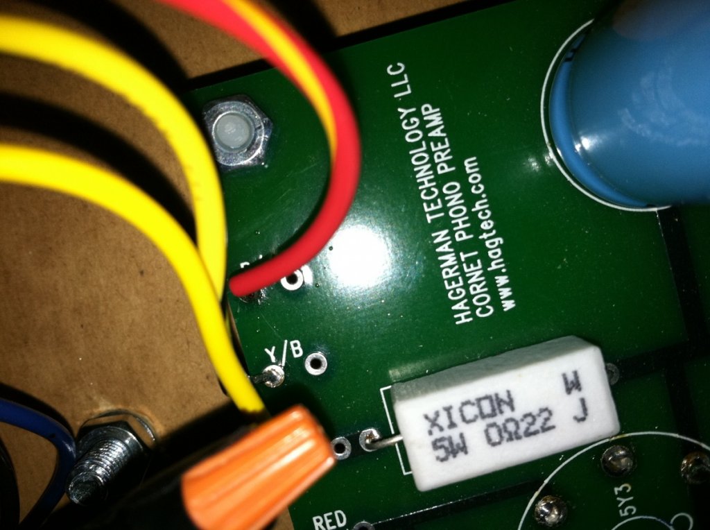
My question is that I thought this was a Cornet as the pcb layout looks exactly as the image provided in the Cornet manual.
However, the pcb clearly reflects a "5Y3" for the rectifier tube. The 5Y3 is used on the Cornet2. The 5AR4 is used on the Cornet.
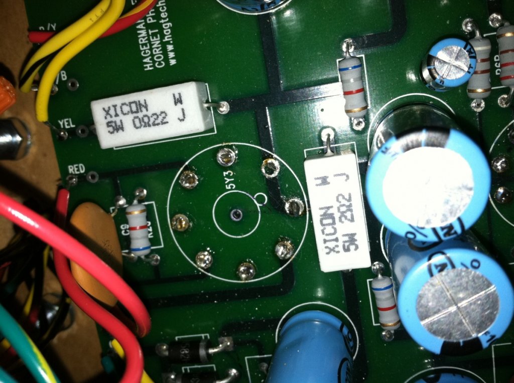
I stopped myself from using the 5AR4 because of this and plugged in a 5Y3. My Cornet as is produces glorious sound, no hum - but only from the left side

I swapped out all of the tubes one at a time with no difference. I swapped the interconnects and the channel being out would switch from right to left. So I believe I eliminated the interconnects or tubes as the culprits. I also reconnected my Wright phono stage and have been playing LPs so its not the rest of my system.
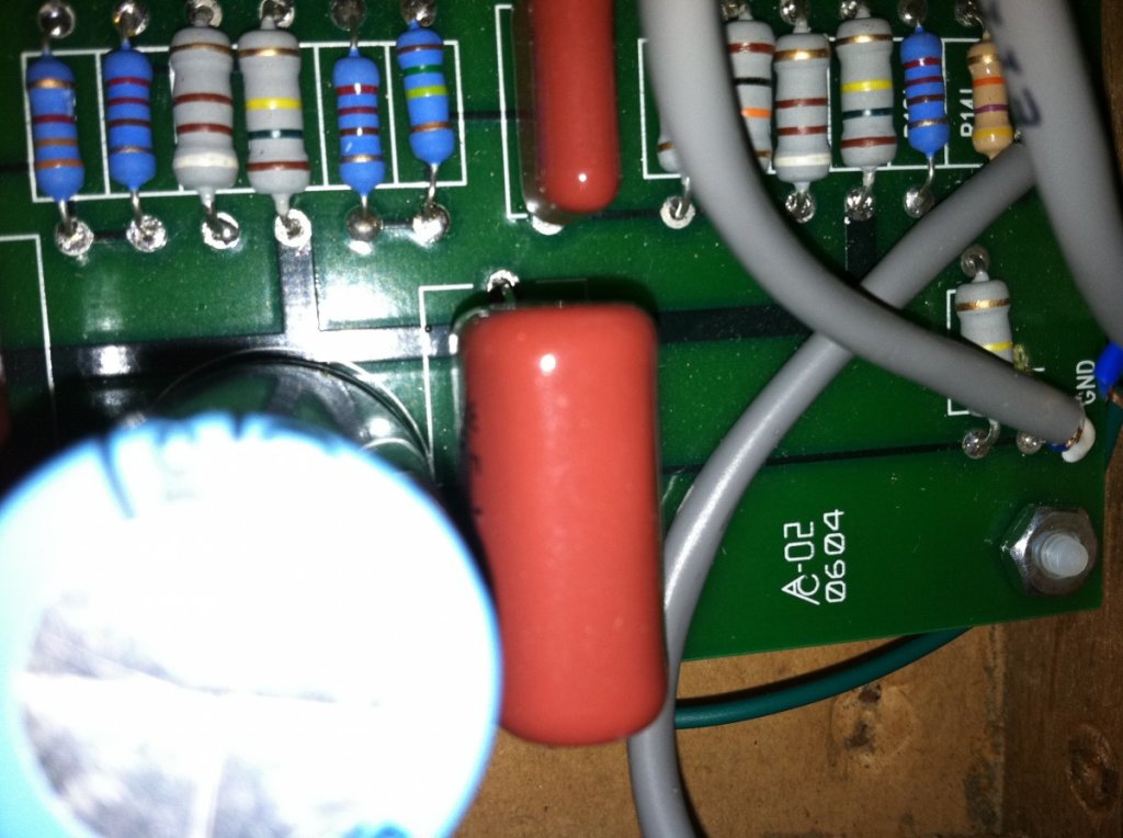
Big question - did I overthink and wrongly use the 5Y3 tube and instead should have used the 5AR4 tube because that is what the rest of the layout supports? The pcb has "C-02 06 04" in the lower, left corner, which I took to mean cornet version 2, June 2004.
However, the upper, right corner simply reflects Cornet Phono Stage.
I am thinking I should plug in an 5AR4 and see what happens. Would a missing channel be caused from using the wrong rectifier tube?
I am a total newbie when it comes to electronics and am not sure about how to do any other testing.
I will go through the PCB and compare all the resistor values and cap values to make sure my friend installed the right pieces.
Any other suggestions would be great!
Thanks! - Troy