Wow, I triggered a lot of mesh. Sorry for that as soon as English is not my native language.
Changing my answer almost instantly.

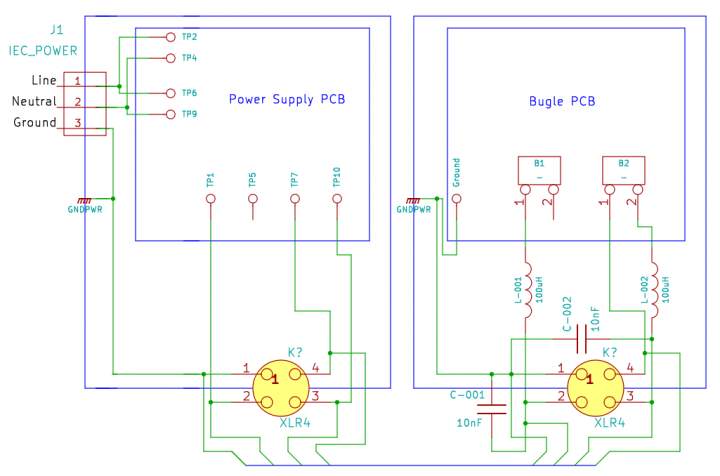
In the first message I was not clear about the additional capacitors and inductances. I use them in a way of "best practice" - so it is not mandatory at all. In my Cornet 2 - it helps, in the Bugle - maybe yes, maybe no. Bugle uses opamps which is not so sensitive to clear power supply. I like to use the precautions (rather cheap and simple) even in not obvious cases.
I am not quite sure where you want the capacitors and inductors.
First - look at
http://hagtech.com/pdf/piccoloman.pdfOn the last page you'll find the schematic. Your attention should be catched by J3 (DC) L1 and C20. J3 is the power supply connector. For powering Piccolo you need only one supply, for Bugle - two. If you repeat the L1-C20 input on both hot (not ground as you mentioned in your questionare) lines - you'll have what I mentioned in my answer.
See the picture in the attachment.
It is possible to solder the capacitors straight on the PCB in place of batteriy holders (in that case - after the L1), but it's still better to solder the "ground side" directly near the place of ground lug on the PCB.
About L1 - you can use something like 652-77F101J-TR-RC from Mouser. The filter to search may have:
- 90-200uH,
- current >50mA,
- small enough to solder directly on the connector,
- low impedance (say < 3 Ohm, which gives us about <0.1V in lost).
As for the type of cap to use I think ceramic caps are used for this application? I got mouser down to about 500 different ones, what other things should I be looking for? Got any favorites?
Be simple for the part. The cap should be:
- small in size,
- 9000pF-100nF of value,
- voltage >50V,
- suitable for high-frequency application (low inductance, switched power supply, RF-type and so on).
Example: 140-50Z2-103M-RC from Mouser.
If you are going to use the second way (soldering directly on the PCB) I'd use film capacitors though, general use one should be enough. You can use the same type as C8, C11, for example: 75-715P200V0.015 from Mouser.
Direction of the inductor matter?
No, it doesn't.
I've seen some posts say you can get rid of c7/ c10 if you are using the power supply and not batteries. Why is this? Should I just leave them be?
No problem, you can save them on place. You have already C3, C6 in the Power Supply section - that is why you can go cheeper and eliminate C7, C10, but it is not rule - just more simple.
With a 4 pin XLR connector, it looks like the shield can act as a chassis ground if I attach it to the shell on each end, and the shell then contacts the chassis connector which is grounded to the chassis through the screws. My question is can I get away with a normal 3 pin XLR now if I use the shield to ground the chassis' together, or do I stick with 4 pin and just not connect the shield to the shells at all, or just one end?
If you manage to connect the 2 chassis by shield - you can go with 3-pin XLR, but I'd use 4-wire under the shield to make the impedance of the connection lower.
Does the male/ female order matter for the XLR cable? I seems like convention is to do male/ female, but it is cheaper overall to do female/ female cable.
Technically there is no difference, so as the only engineer and user of the system you can use any version.
I started looking for a cable to use with my 4 pin XLR connectors and what a nightmare. I can't find a shielded, 4 conductor, 20AWG, cable that I can buy by the foot at all. Any ideas for this? Good sites to buy by the foot that wont set me back 40$ a foot?
I've bought on
http://www.partsconnexion.com, but on local market as well. It is possible to use 2 plain (1 or 2 wire) shielded cables (something like this:
http://www.partsconnexion.com/product7558.html ) with or without outer shielding like this:
http://www.partsconnexion.com/heatshrink_braid_tinned.html In my case to made the cable good looking I use something like this:
http://www.partsconnexion.com/heatshrink_braid_poly.html outside the copper mesh.
So go with the 24V switch and just put wire in R3 and R10 correct?
Yes, I think it'll work. Instead of connecting to R10 you can try to connect to the middle point also.
Any point of getting an IEC power entry module with a filter?
I don't think it is nessesary.