X-SLS Amateur Build

0 Members and 1 Guest are viewing this topic. Read 1998 times.

jonsk2514

Re: X-SLS Amateur Build
« Reply #20 on: 22 Apr 2023, 06:34 pm »
As I noted the cutout in each brace has the corners rounded.  This was done with a 3/8” quarter round.  Then I made a small bevel on the braces on the corner that matches with the glued back to side corner where glue extruded while being clamped and then hardened.  The bevel on the braces precluded the need to chip out the extruded and hardened, which allows the brace to fit in unimpeded.


Next is dry fitting the braces to the cabinets.  This is where they become custom fit to the cabinets.


This was done with the un-glued side clamped in place to get the width right and then with the front clamped in place along with that side.  Clearance with the top is a little harder to judge as the braces can’t be seen, so I just look for the top fitting flush with the sides, top and bottom.

It also turns out that the braces were slightly out of square.  Squaring them was easily accomplished along with the sizing of the braces.

I glued the braces using TiteBond Quick and Thick glue.  This glue is designed to fill small gaps, which will exist with these braces as the butt joints all of the way around them.


I use strapping film to protect the front panel from being glued by any extruded glue.


The unglued side is also protected from extruded glue with strapping film.

And then clamps, clamps, clamps at each brace to make sure they are each pressed into place.


The half braces take a little more effort.


It is first put into place with glue.

The it is clamped onto place.


The silver clamps are adjustable Harbor Freight welding clamps that worked well in this case with a little help with a piece of 2x4.

The sides are clumped with a parallel clamp to ensure the sides are pressed in.

jonsk2514

Re: X-SLS Amateur Build
« Reply #21 on: 30 Apr 2023, 07:34 pm »
It is crazy that glueing on one side has taken as many or more clamps as any other step in this whole build.  But it is easy to see why.


I should have taken a picture of how the glue was laid in, but I failed  :P  I used the Original Titebond glue on the 3 edges being joined with the top, bottom and back panels.  I used Titebond Quick & Thick on the edge of each of the braces.  The Quick and Thick will bridge any gaps between the braces and the side.  With the side lightly clamped in place the front panel was put in with the strapping film to ensure it is not inadvertently glued in.  Including the front is necessary to ensure the side panel is appropriately pressed into place on the back panel and to ensure the resulting width, when the glue sets, will allow the front to fit later on.

There are clamps side to side and front to back at each braces as well as at the ends.  There are end to end pipe clamps.  A mistake I made was losing track of where I placed the clamps and missed placing one on the side panel at the corner of the front panel and the top panel.  This meant that the side wasn’t pressed into the top as well as I would have liked.  But it will be okay.

Here are the side and back to top braces being glued in places.  I again used the Titebond Quick & Thick to bond these in place, as I did in the X-LS build.  I could have PL Max, as other have done.  Not sure if there is any real difference in this application.  I just like that the Titebond is specifically made for wood.


I did glue these braces into the correct end.  The cabinets are upside down to facilitate the glueing process.  And the brace is actually straight across  :eyebrows:

Glueing the front panel on is close at hand, so it is time to be thinking where to put the crossover board. In all honesty, this speaker is tight inside.  There are more parts to the crossover than will fit on the back wall of the speaker, without having to make a stacked sections of the crossover.  The plan is to mount the crossover on side wall.  This way it will be long enough to fit all of the parts.


corndog71

  • Full Member
  • Posts: 1631
  • Some people call me Rob.
Re: X-SLS Amateur Build
« Reply #22 on: 30 Apr 2023, 07:49 pm »
You can tighten things up a bit.


jonsk2514

Re: X-SLS Amateur Build
« Reply #23 on: 1 May 2023, 05:24 pm »
Nicely done  :thumb:

Thanks for sharing.

I thought about doing that but wasn't sure how to twist the wires together within that space as Danny has shown in his video. 

It looks like you have wound or wrapped one wire around another wire, instead of actually twisting them together.  Did I get that right?  :scratch:  If that works okey, then I’ll be able to do that.

corndog71

  • Full Member
  • Posts: 1631
  • Some people call me Rob.
Re: X-SLS Amateur Build
« Reply #24 on: 2 May 2023, 12:04 am »
Nicely done  :thumb:

Thanks for sharing.

I thought about doing that but wasn't sure how to twist the wires together within that space as Danny has shown in his video. 

It looks like you have wound or wrapped one wire around another wire, instead of actually twisting them together.  Did I get that right?  :scratch:  If that works okey, then I’ll be able to do that.

The key is a good physical connection before soldering.  As long as things are tight you don’t have to go crazy with twisting wires.  And then anchor the crossover to a small board with zip ties.

jonsk2514

Re: X-SLS Amateur Build
« Reply #25 on: 2 May 2023, 04:11 pm »
I gave the crossover layout a second try and was able to compact the size of it similar to the above posted by Corndog71.


Ignore the board it is on except for the outline which represents the available space at the back of the speaker where it will be accessible through the hole for the bass driver.

Basically the negative will be through the center of this cluster and the positives to the drivers come off the left and right sides.  The bass circuit is simple.  The input to the bass coil will be at the bottom and the output to the driver is at the top left, with the Cap connecting that to the negative.  The tweeter circuit is more complex, but the Caps and resistors stacks well, with the input to this circuit being to the left side of the bottom resistor (green).  From there back and forth such that the output to the tweeter driver is out the right side, with a resistor back to the negative.

As can be seen, no wires are connected.  But based on the above comment, it will be easy to make good connections between the wires before soldering.  From there, the section can be arranged on a board and zip tied in place.  The “blue stuff” is a non-oily mounting putty that I plan to use between parts to keep them from having a chance for buzzing or otherwise.

maty

Re: X-SLS Amateur Build
« Reply #26 on: 2 May 2023, 05:14 pm »
The tiny red capacitor (bypass) has me intrigued, what brand is it?

Audyn CAP Q4 MKP Polypropylene Capacitors 400V 5%


Hobbsmeerkat

  • Industry Participant
  • Posts: 2334
Re: X-SLS Amateur Build
« Reply #27 on: 2 May 2023, 07:13 pm »
Its a 0.1uF JB JPX cap.
It's the replacement for the Gen 2 Sonicap bypass we used to offer on our base level kits.
They're quiet nice for their price.

maty

Re: X-SLS Amateur Build
« Reply #28 on: 2 May 2023, 07:16 pm »
Thank you very much!

maty

Re: X-SLS Amateur Build
« Reply #29 on: 2 May 2023, 07:29 pm »
I think you will be interested. We know that the human ear is insensitive to distortion up to a few hundred Hz -> it makes sense to use laminated inductors in low-pass filters ONLY at frequencies < 400 Hz (approx.)

QAcoustics Concept 500, White paper, page 15


jonsk2514

Re: X-SLS Amateur Build
« Reply #30 on: 10 May 2023, 02:06 pm »
Still working on the build.  Making posts has been lagging though. 

As shown in my previous post, I was able to come up with a more compact arrangement. I like this better and it will mount in the back of the cabinet.

The tweeter circuit is the most complex with the most parts, so I broke it down into sections and made the connections in steps.  The first was to make connections between paralleled parts.


Then these parts were connected together.


The 180 deg bends were done after twisting the wires together.

Lastly the coil to negative and the resister to negative were connected.  The resistor to negative is on top of the  upper cap and, even though it looks to cross close to the connection below it, it is actually a ways away from it.  The actual connection of this resistor is to the right end of the upper cap.


As noted below the blue stuff is mounting putty that holds the parts together and will keep them from vibrating against each other.

The bass circuit is much more simple with only one connection between the the coil and cap.  This was done by clearing off some varnish from the coil wire.  The connection was made a little ways from the end so the end can be used to connect to the speaker wire.

Next - Soldering.
Really it is not very hard.

Tyson

  • Full Member
  • Posts: 10542
  • Audio - It's all a big fake.
Re: X-SLS Amateur Build
« Reply #31 on: 10 May 2023, 04:11 pm »
I like your work style - patient and thorough.

jonsk2514

Re: X-SLS Amateur Build
« Reply #32 on: 25 May 2023, 08:43 pm »
I like your work style - patient and thorough.

Thanks.  :thumb:

Once again other things have come up that have delayed my progress.

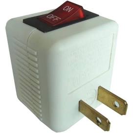
One of which was the failure of the power wire to the motor on my drill press.  No damage other than the plug broke when I tried to unplug it.  Time to fix it as it is needed for several of the next steps in this build.  But as with all projects I do, one thing tends to lead to another.  I had to take the motor off to fix the wire, so I thought I would replace the motor with a slightly newer and more powerful one I have.  I got that one all wired up and re-did the mounting as that was different.  Fired it up…   :shake:  Oh Crap! It rotates in the wrong direction…. I feel like  :banghead:  Back to the old motor.   This, too, required the mounting to be re-done in order to align the new pulling I put on it with the other pulley.  Then the switch fell apart when I tried to put the wires on it…  :bawl:  Well, it is all back together now, running well and has been put it to good use.

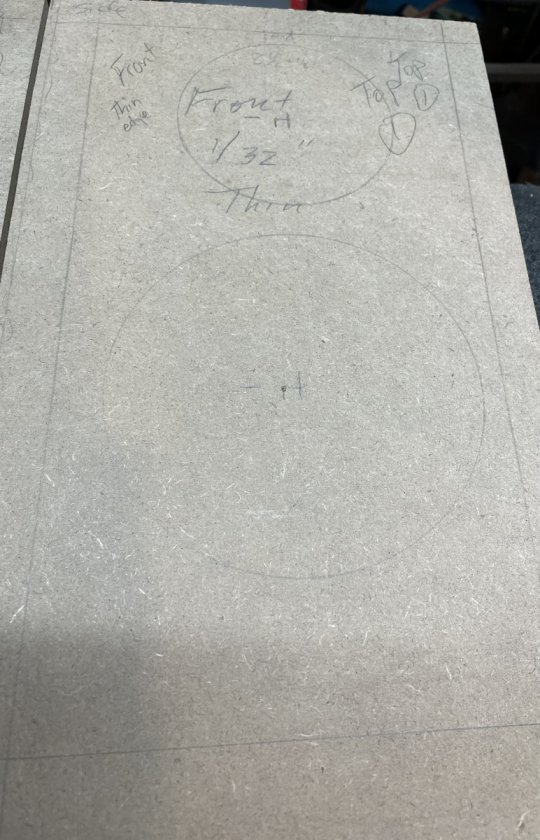
I made the mounting boards for the crossovers.  As with my past efforts, these are made from 3/16-ish lauan cut to fit on the back panel between the braces and inline with the bass driver.  These will be mounted on 1-1/8” high blocks so No-Rez can be installed beneath them.  The newly refurbished drill press made quick work of making holes for the crossover tie downs and in the mounting blocks.


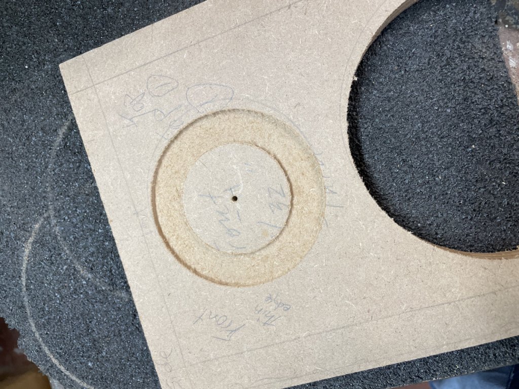
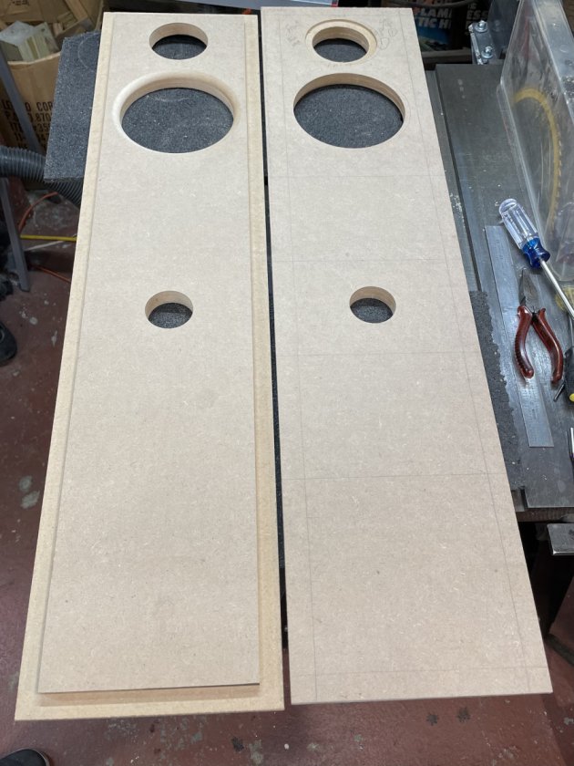
Hopefully progress will proceed with some regularity now…  :?  We’ll see.  Time to start cutting holes for drivers and binding posts.

Yes, binding posts.  Tube connectors would be lost on the system this will be going into. :roll:  And don’t even ask about the speaker wire I am currently using.   :no_speak:

But I did go through and replace all of the magnetic parts with non magnetic brass parts as I did for my past progects.


Replacement parts