I had assumed that changing the input impedance would automatically change the output impedance too. This is very interesting!
Yes and no. Input is nearly fixed for any given impedance level whereas output impedance varies as you change volume (attenuation).
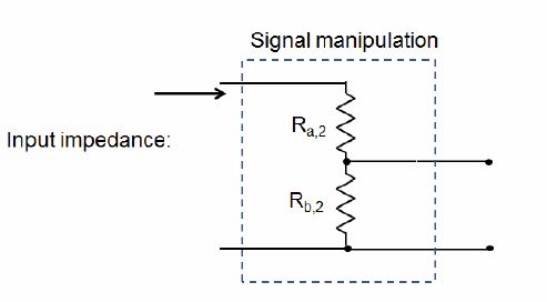
Input ImpedanceWhether it's a potentiometer or a pair of series/shunt LDRs, what you have is a voltage divider. With pots the input impedance is always fixed. It's the rated resistance of the pot from input to ground which per the sketch below is Ra+Rb. Ground is the bottom horizontal wire and the wire coming out between Ra and Rb is the pots wiper ...OR.. the output of the voltage divider (same thing).
With LDRs is can also be fixed but not necessarily. It depends on how you control the LDRs. In the sketch the series LDR is Ra and the shunt is Rb. Again, it's the sum of Ra and Rb that determines the input impedance. Unlike with a pot where this sum is fixed, with LDRs you must control each of these independently. Which we do in our LDR preamps.
The way a voltage divider works is per this formula: Vout = Vin x Rb/(Ra + Rb) or Vout/Vin = Rb/(Ra + Rb). The resulting attenuation expressed in decibels is dB = 20*log(Vout/Vin)
What we do in our LDR preamps where you can change the input impedance is we compute the combinations of Ra and Rb that give us the 70 attenuation steps we need while trying to maintain the sum of Ra + Rb equal to the target input impedance. In practice this is not possible while also attenuating down to -60 dB so what happens is the impedance has to go up from the target as volume gets turned down low (usually around step 20 and down).
 Output Impedance
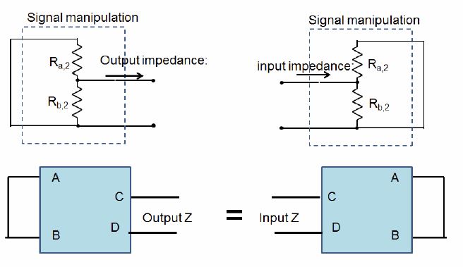
Output impedance is different. It's not fixed. Not in a pot and not with LDRs either. The way to look at output impedance is just flip it around and look at it as though it was just another input impedance with the output jumpered. That's illustrated below.
Unlike with input impedance where Ra and Rb were in series, here Ra and Rb are in parallel. With parallel resistors(impedances) the formula is R = Ra x Rb/(Ra + Rb)
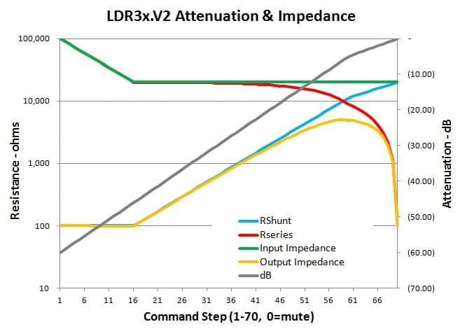
Tying all of this together you get something like the graphic below. This shows an attenuator with 20k input impdance - the green line. Note that it's constant until you get down to around -50 dB and then it increases in order for the attenuation to continue down to -60 dB. It's just how the math works.
Now note the output impedance which is the yellow line. As volume increases it rises from a very low value (100 ohms) and then peaks at -6 dB (loud! ) and abruptly falls back down to 100 ohms as attenuation approaches 0. This is how every pot works in every preamp ever.
Of course all the above is simply looking at the attenuator in isolation and not hooked up to anything. When you attach an amp to the output of the attenuator you add an additional resistance in parallel. So you have to do the R = Ratten x Ramp / (Ratten + Ramp) calc to get the effective impedance as seen by your source (DAC, phono preamp etc. )