Christopher,
I've moved this post to its own thread as its not specific to Felicia and is a generalized question about rewiring transformers.
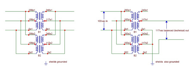
Short answer - Yup, you can rewire this C-core transformer to function as a 100v to 117v balancing transformer, albeit at a derated, half capacity.
Standard Caveat - this is not something for a beginning DIYer. You are dealing with lethal line voltages. If you are not competent with procedures and practices in dealing with such, DO NOT!!! muck with stuff that can kill you. Nuff said.
Note to all - Christopher is in Japan, and I'm assuming his intent is to derive a 117v balanced (technical) AC for powering his 115-120vac components from his 100vac mains voltage.
Step 1. Buy yourself a housed Variac that plugs into you wall mains and preffably has a wall socket output. Go to Ebay, do a search on 'Variac' and it will become clear.
http://search.ebay.com/search/search.dll?sofocus=bs&sbrftog=1&from=R10&satitle=%28variac%2Cpowerstat%2Cvariable+transformer%29&sacat=-1%26catref%3DC6&bs=Search&fsop=1%26fsoo%3D1&coaction=compare&copagenum=1&coentrypage=search&fgtp=&sargn=-1%26saslc%3D2&sadis=200&fpos=11215&ftrt=1&ftrv=1&saprclo=&saprchi=Chris, as you can source these marvelous surplus transformers so easily and (I hope) inexpensively, I assume sourcing a surplus Variac should be easy. You've certainly invested enough in a rather esoteric collection of iron to justify such a small incremental expense.
I'm saying this because its far more difficult to kill oneself when mucking about with a transformer's configuration, when you're feeding it 20VAC as opposed to 100-120vac or 200-240vac. YOu simply need to make note of the fact that proportionately, if you feed a transformer 20vac instead of your intended 100vac, your measurements on the arse end will be 1/5th of the 100vac measurements.
If you can't look at the picture of these transformers and suss out their internal configuration (schematic), noting that the different, smaller gauge higher voltage windings tell you some very important information, you shouldn't be messing with an unknown entity that can kill you. This doesn't mean you're a less worthy or intellegent person, it simply means you're not a total dweeb.
When you've sourced your variac, feed it from one of the many, many transformers that you bought that are already configured as an isolation transformer, with floating outputs, i.e. 'neutral' not rebonded to ground on the isolation transformer's secondary. You'll be able to ramp the isolated variacs voltage, and at 20vac, the 'danger' is roughly 1/25th of that at 100vac. [yes, there are all-in-one isolated variacs, which are typically variable transformers, rather that variable autoformers.]
First, hook up via the variac a voltage to the 0-200v primary leads. On the secondary, measure the voltage between 0-240, 0-117, and 117-240. If those voltages of the latter 2 are EXACTLY equal, and half of the first, the secondary windings are really 0-120-240 and the transformer does not need rewiring, simply input 100vac to the 0-200vac primary connections and take 120vac balanced from the 0-240vac secondary after grounding the 117 output.
If not, long story short, you'd do exactly as you proposed

, and rewire the tranny from this to that......
.
and if its not 100% clear, PM or better yet, Skype me.
While I have talked about configuring a specific transformers, this was a 'standard' for the Felicia. I'm simply unwilling to publically discuss in detail reconfiguring arbitrary power transformers, due to the very real danger. I'm far more willing to do so via phone or for international participants, Skype
Christopher - you're driving me up the wall. Rather than duplicate a single Felicia with Japanese sourced components equivalent to the signal A41, which would have been a trivial task for you, you've chosen to skip the rinky dinky stuff and and go for massive overwheming force of iron. And when all is said and done, you've yet to experience any benefits. That being said, you've amassed one of the 'purtyest', lovely, most sophisticated collections of power transformers that I've ever seen. I'm jealous.


