Back EMF

0 Members and 1 Guest are viewing this topic. Read 20320 times.

gerado

  • Jr. Member
  • Posts: 123
Re: Back EMF
« Reply #20 on: 8 Nov 2007, 03:23 am »
NNNOOOOooooooo :duh: I thought I was going to be free of passives

Davey

  • Full Member
  • Posts: 1481
Re: Back EMF
« Reply #21 on: 8 Nov 2007, 05:09 am »
Hi Theo,

Absolutely, yes.  The Zobel at the speaker corrects for phase shift at the speaker, which has benefits for an amp with gnfb.  The DEQX corrects for phase shift at the line level around crossover, and this is at a totally different point in the circuit.

Cheers,

Hugh

And it's a different type of phase correction too.

It's certainly possible to Zobel (impedance) correct all drivers to essentially resistive but still have considerable phase shifts within the final system  acoustic response related to the crossover filters, etc.

I hope everyone's clear on that distinction.

I'm not sure how impedance angle correction translates directly to improved imaging, but I'm here to learn.  :)

Sorry to butt in.

Davey.

« Last Edit: 8 Nov 2007, 05:26 am by Davey »

AKSA

Re: Back EMF
« Reply #22 on: 8 Nov 2007, 06:05 am »
I'm not sure how impedance angle correction translates directly to improved imaging, but I'm here to learn.
Quote

Davey,

I'm glad we got that right......  thank you for your visit.

Consider this:

A less reactive driver, notwithstanding phase shift in the crossovers, will be easier to drive for the amp.

Reason:  voltage and current will be less out of step, so voltage feedback to a global negative feedback amp will more accurately reflect current in the voice coil.

The tricky area of nfb control for any gnfb amp is around crossover, where outputs are in transition.  This region, typically 2.45Vpp, is difficult to control because of the highly non-linear behaviour of the devices at switch on/off.  Furthermore, the voltage amplifier must contend with rapidly changing impedances in the output stage at this point;  since it's source impedance is high, this hugely influences open loop gain at this crossover point, further fudging the detail.

The tiny spatial cues of any performance, particularly reverberation, are found in that first 100mW of signal, and the reason I suspect why NP and others highlight the 'First Watt'.

If the feedback has less phase shift at this very low level, then very low amplitude signals should be better rendered through the drivers.

This is, I think, the reason why the imaging is better.  However, don't listen to me, you should try it, as I have, to hear for yourself.

Hugh

kyrill

Re: Back EMF
« Reply #23 on: 8 Nov 2007, 09:30 am »
WHat DEQX is doing is measuring phase shift  with a microphone, so measuring the shift in the speakers output before the Xovers are in the path

It also tells you this. then it adds corrections to the calculation of the crossovers while the crossovers will never leave the preamp
it measures again after the filter is included to make sure

IS there still phase shift left to be indirectly corrected by a zobel?
reading above story FF corrections at line level canoot really correct those phenomena albeit it will  be less when there is no crossover at all?

andyr

Re: Back EMF
« Reply #24 on: 8 Nov 2007, 09:39 am »
NNNOOOOooooooo :duh: I thought I was going to be free of passives

Yeah, mate, but maybe it's not so bad?  :D

Passive XOs have series inductors (for LP filters) and series capacitors (for HP filters), so by going active, you do away with these components which are "in the way" between the amplifier and the driver.  :o

Zobel networks are in parallel with the driver, so you should think of them as actually part of the driver itself!  :o  They don't "stand in the way" of the amp controlling the driver ... so you still have all the advantages of an active system.

To me, the only point that still needs defining (Hugh - are you listening?  :D ) is ... can you implement Zobel networks as part of an active XO?  Or must they by definition be passive, parallel components?

Regards,

Andy

AKSA

Re: Back EMF
« Reply #25 on: 8 Nov 2007, 10:07 am »
Andy, it's a pleasure!

A Zobel is a phase shifting network, a resistor and cap in series, placed across a transducer.

Even with DEQX nulling, there will still be phase shift appearing at the amp fb node.  So yes, a zobel at the driver will largely prevent this.

This is not to condemn the DEQX, it's a very clever piece of kit I much admire.

Cheers,

Hugh

andyr

Re: Back EMF
« Reply #26 on: 8 Nov 2007, 10:22 am »
Andy, it's a pleasure!

A Zobel is a phase shifting network, a resistor and cap in series, placed across a transducer.

Cheers,

Hugh

Hi Hugh,

Yes a "Zobel" driver-impedance-correction network is a res + a cap in series with the driver ... but can you implement driver impedance-correction using "an active" piece of circuitry?  :? Or is the only way you can "tame" the driver by putting the Zobel across it?

Regards,

Andy

kyrill

Re: Back EMF
« Reply #27 on: 8 Nov 2007, 11:38 am »
 for those ( like me) who didn't know to much how to implement a Zobel:


Neutralizing L(e) with a Zobel
by
John L. Murphy
Physicist/Audio Engineer
 
A Zobel is a series resistor-capacitor (R-C) network that is connected in parallel with a loudspeaker driver in order to neutralize the effects of the driver’s voice coil inductance L(e). Figure 1 below shows a Zobel consisting of resistor R1 and capacitor C1.

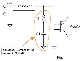
Figure 1: A Zobel Network Consisting of R1 and C1

Because a loudspeaker’s voice coil is itself an inductor, the impedance of the driver increases with frequency much like an inductor. When a woofer is used with a passive crossover the driver’s L(e) has the effect of spoiling the crossover filter action. A Zobel can be used to restore the impedance of the driver to the nominal value in the high frequency range. This will allow the crossover filter to operate more effectively in the high frequency range where it is used to attenuate the highs going to the woofer.
Without a Zobel network the impedance of a typical woofer looks something like Figure 2 below. Notice the rise in impedance to the right. The peak at the left is the resonance peak of the driver. If this were a tweeter we would want to neutralize the resonance peak. Since we are discussing woofers here, it is the rise in impedance through the crossover region that concerns us.


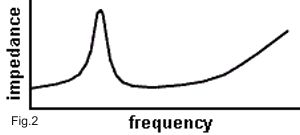
Figure 2: Impedance of a Driver without a Zobel

With the addition of a properly designed Zobel network the impedance will re changed to look like Figure 3 below. Now the woofer exhibits a flat (resistive) impedance through the crossover region in the midrange and high end.

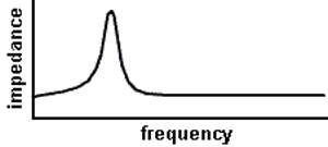
Figure 3: Impedance of a Driver with a Zobel added

You can design a Zobel network for your woofer by starting with a resistor (at least 10 Watt) equal to the nominal impedance of the driver. For an 8 Ohm woofer you would use an 8 Ohm resistor, 4 Ohm woofer, 4 Ohm resistor, and so on. Next, calculate the value of the capacitor from the nominal impedance and the driver’s L(e) value. Use the following formula:
                                                           
(where L is in Henrys and R is in Ohms, and C is in Farads)
Concerning component selection, just use the closest available 5% value. Do not feel as if you have to match the value exactly. Remember, most manufactured systems are done with component specifications no tighter than about 5%. You will find many 10%, and even 20% components in consumer electronics products. As you progress to 1% components you are moving into the "precision" zone appropriate for instrumentation and military grade systems. The more accurate the better, certainly, but 5% is usually plenty accurate for crossover components.
The power (wattage) rating requirement of a crossover resistor depends strongly on its location in the circuit. Your Zobel resistor can probably be rated as low as 10 or 20% of the power rating of your woofer. On the other hand, a tweeter attenuator resistor might need to be rated as high as 10 TIMES the power rating of the tweeter. If you need to be absolutely certain that you are staying within the power rating of your components, you will need to do a detailed power dissipation analysis of the crossover circuit.

Example:
Driver Nominal Impedance = 8 Ohms
Driver L(e) = 1 mH = .001 H
 
R = 8 Ohms (10 W minimum rating)
C = 15.6 micro Farads (film type capacitor preferred)
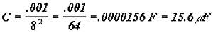
                                                   

Listening Test
Try this test. Listen carefully to the woofer in your system with the crossover connected. Alternately connect the Zobel network in and out of the circuit. You should notice a reduction in the highs coming from the woofer when the Zobel is connected.

Summary
Adding a Zobel to a woofer will allow the passive crossover to work more effectively. The impedance of the woofer will also be restored to the driver’s nominal impedance throughout the high frequency range. This technique allows the use of crossovers designed for resistive loads to operate as intended.

Jens

  • Full Member
  • Posts: 345
Re: Back EMF
« Reply #28 on: 8 Nov 2007, 11:49 am »
Andy, it's a pleasure!

A Zobel is a phase shifting network, a resistor and cap in series, placed across a transducer.

Cheers,

Hugh

Hi Hugh,

Yes a "Zobel" driver-impedance-correction network is a res + a cap in series with the driver ... but can you implement driver impedance-correction using "an active" piece of circuitry?  :? Or is the only way you can "tame" the driver by putting the Zobel across it?

Regards,

Andy
Hi Andy,

Most "active cicuitry" is situated at signal level and thus is not connected with the actual, physical drivers. No corrections that you make at signal level will be able to affect the power amp / speaker driver interface.

So, if you want to improve that interface, an impedance correction may in many cases be a boon.

One could look at impedance correction as a way of improving "cooperation" between power amp and speaker driver.

An important thing, which has not been touched upon so far in this thread, is that impedance correction networks should always be measured/calculated with the drivers mounted in their enclosures, as enclosures have a marked effect on impedance behaviour.

gerado

  • Jr. Member
  • Posts: 123
Re: Back EMF
« Reply #29 on: 8 Nov 2007, 12:46 pm »
Boys this thread is so full of such useful information it is making my brain swell and pressing too hard against the inside of my cranium.  :o
This has got to be one of the most useful and practicle  threads for some time.

Kyrill that is a gem of a little article!

Andy all is not lost then  :thumb:, good point about zobel being in parallel.


So taking this discussion further

1.The base driver one would expect has a greater back EMF than a tweeter because of the sheer size of the coil(Inductor) of the driver. However are the sound effects on the different size drivers all relative and the adverse effect on sound degradation pretty much shared equally among the drivers albeit at different frequencies.
I suspect the ear being what it is will be sensitive to certain frequencies more than others and the effect more noticeable at certain frequencies?
ie is a zobel just as important for the base , mid or tweeter.

2. Published data on driver behavior is probably inaccurate, or at least should be verified. More so if the impedance changes in the enclosure, as Hugh states. How do you measure impedance of a driver in real life?

3. If you plan to use SET amp all this is irrelevant?

Im going to be one happy Zobeler  aa

Davey

  • Full Member
  • Posts: 1481
Re: Back EMF
« Reply #30 on: 8 Nov 2007, 02:58 pm »
I'm not sure how impedance angle correction translates directly to improved imaging, but I'm here to learn.
Quote

Davey,

I'm glad we got that right......  thank you for your visit.

Consider this:

A less reactive driver, notwithstanding phase shift in the crossovers, will be easier to drive for the amp.

Reason:  voltage and current will be less out of step, so voltage feedback to a global negative feedback amp will more accurately reflect current in the voice coil.

The tricky area of nfb control for any gnfb amp is around crossover, where outputs are in transition.  This region, typically 2.45Vpp, is difficult to control because of the highly non-linear behaviour of the devices at switch on/off.  Furthermore, the voltage amplifier must contend with rapidly changing impedances in the output stage at this point;  since it's source impedance is high, this hugely influences open loop gain at this crossover point, further fudging the detail.

The tiny spatial cues of any performance, particularly reverberation, are found in that first 100mW of signal, and the reason I suspect why NP and others highlight the 'First Watt'.

If the feedback has less phase shift at this very low level, then very low amplitude signals should be better rendered through the drivers.

This is, I think, the reason why the imaging is better.  However, don't listen to me, you should try it, as I have, to hear for yourself.

Hugh

Hugh,

Interesting explanation.

I have tried it...on a number of occcasions....dating back many years.  :)  On the midrange driver of my Orion setup too.  :)
I'm not convinced this will have an audible effect when used with amplifiers that are operating like true voltage sources.  Or close.  I believe the amplifiers I've been using satisfy that aspect.

When set up I was also careful to verify (made measurements) that the RC network was not changing the applied response to the driver relative to the case with no Zobel used.

I would venture to say that if audible differences are noted with this application then the amplifier itself has less than ideal characteristics and the application of the Zobel is skewing the response.

Also, I'm wondering if this type of RC Zobel is recommended then why stop there.  Why not add an LCR conjugate in shunt with the driver to address driver resonance at lower frequenices as well??

My two cents.

Dave.

AKSA

Re: Back EMF
« Reply #31 on: 8 Nov 2007, 08:16 pm »
Hi Dave,

Quote
Also, I'm wondering if this type of RC Zobel is recommended then why stop there.  Why not add an LCR conjugate in shunt with the driver to address driver resonance at lower frequenices as well??

We did try that, and found that the components were very expensive (10,000uF electro and very large inductor) and the audible benefits were zip......

I think you are right about the amplifier.  All gnfb amps, regardless of how good or bad their design is, are sensitive to phase shift at the driver.

Hugh

Steve Eddy

  • Full Member
  • Posts: 877
    • http://www.q-audio.com
Re: Back EMF
« Reply #32 on: 8 Nov 2007, 08:23 pm »
All gnfb amps, regardless of how good or bad their design is, are sensitive to phase shift at the driver.

Well that's simple enough. Don't use gnfb amps. :green:

se


AKSA

Re: Back EMF
« Reply #33 on: 8 Nov 2007, 08:55 pm »
Steve,

You are quite right!!

Why not use a transformer??    :duh:

Cheers,

Hugh

Steve Eddy

  • Full Member
  • Posts: 877
    • http://www.q-audio.com
Re: Back EMF
« Reply #34 on: 8 Nov 2007, 10:24 pm »
Steve,

You are quite right!!

Why not use a transformer??    :duh:

Brilliant!

I'll bring the transformers. You supply the follower output stage.

PARTY AT HUGH'S!!!!!!  :rock: :guitar: :drums:

se


gerado

  • Jr. Member
  • Posts: 123
Re: Back EMF
« Reply #35 on: 8 Nov 2007, 10:27 pm »
WHAT TIME!!!! :beer:

Davey

  • Full Member
  • Posts: 1481
Re: Back EMF
« Reply #36 on: 8 Nov 2007, 11:52 pm »
Maybe it would be easier to just find speakers that are a resistive load?  Oh wait, they already make those.  :)

You guys are funny.

Dave.

AKSA

Re: Back EMF
« Reply #37 on: 9 Nov 2007, 01:28 am »
Thank you for your courtesy, Dave,

You are a patient man, albeit with no sense of humour!   :lol:

Hugh

andyr

Re: Back EMF
« Reply #38 on: 9 Nov 2007, 02:46 am »
Maybe it would be easier to just find speakers that are a resistive load?  Oh wait, they already make those.  :)

You guys are funny.

Dave.

Yes, they do Davey ... as you know well!  :D  Maggies!!   :o

Regards,

Andy

andyr

Re: Back EMF
« Reply #39 on: 9 Nov 2007, 02:48 am »
Hi Andy,

Most "active cicuitry" is situated at signal level and thus is not connected with the actual, physical drivers. No corrections that you make at signal level will be able to affect the power amp / speaker driver interface.


Thanks, Jens for putting the final piece of the jigsaw in place!  :D

Regards,

Andy