NX-3 Bravo Towers, Standard Build

Rifleman455

  • Jr. Member
  • Posts: 26
NX-3 Bravo Towers, Standard Build
« on: 14 May 2026, 05:31 pm »
I decided to try the NX-3 Bravo towers a la Hobbs for my system.  I also plan to make the enclosures myself because I like to do a bit of Do-It-Yourself (DIY) in my audio world.  I bought the speaker kit from GR Research so all I must do is build a pair of cabinets that my spouse will allow in the living room.  No problem, right?  I plan to build the cabinets as shown in the plans from GR Research.  The only deviation is to add 1/4" slots in the sides to locate the internal braces (more on that later.)

This is not a tutorial on building cabinets or using power tools correctly, just a story of what I did.  I won’t be held liable for anything others do.  If I can answer questions about what I did, please ask!  If you have suggestions for others to improve their build experience or safety, please post them so we all can learn!

I plan to butt-join most of the cabinets using #20 biscuits but will use a router to make ¼” slots in the cabinet sides to hold the braces for easier assembly.  To fit the slots, the internal pieces need to be 7 inches wide instead of 6 ½ inches.

I don’t have a wood shop, but I have a garage with tools in it (and a lot of junk.)  Instead of trying to cut a 4’ by 8’ panel on my table saw and hope to get square edges, I’ll use a track-saw guide (Milescraft 1409) with my 7-1/4” circular saw.  This tool is more affordable for me compared to true track saws that I may only use once.  The track-saw guide lets me make 50” cuts unless I buy another 55” guide track (Milescraft 1408,) so I’ll plan my cutting accordingly.  I also learned that Medium Density Fiberboard (MDF) panels are an inch longer and wider than plywood, so the sheet was 49 by 97 inches.

I bought a 4’ by 8’ sheet of ¾” MDF and had the store cut it at 44” to make it easier to carry.  This is shown as Cut (1) in Figure 1.

Figure 1: Cut Layout for 4-by-8-foot sheet of MDF

I trimmed two adjacent square sides to be my guides and then cut the panel down from 44 to 42 inches.  See Figure 2.  Then I ripped the front and back panels from the 44” sheet with the track-saw guide, cutting them 1/8-inch wider than specified so I could run them through my table saw later to make all the panels the same seven- or eight-inch widths.  I also ripped two long seven-inch planks from the remainder for the internal panels B, D-E, and F.  See Figure 3.

Figure 2: Cut Smaller MDF Sheet to 42 Inches Long

Figure 3: Smaller MDF Sheet Cut into Fronts, Sides, and Braces

From the 53-inch panel, I cut a slab 40-1/2” tall for the side panels and internal braces A, F, and G.  I then ripped the cut-off panel down to ten inches wide for the tops and bottoms.  Then I ripped the side panels from the 40½” sheet with the track-saw guide, cutting them 1/8-inch wider than specified so I could run them through my table saw later to make all the panels the same ten-inch widths.

I cut the fronts, backs, tops, and bottoms eight inches wide on my table saw.  I cut the braces A, B, D-E F, G and H to seven inches wide on my table saw.  The B braces (labeled B1 and B2 in Figure 1) have 5 ½” semicircular cutouts on each end that are easier to make as full circles than as semicircles.  I switch to my router circle-cutting guide (Milescraft 1219) and divided a seven-inch-wide plank into 10-1/8” sections to allow for the 1/8” kerf on my table-saw blade.  I still had to cut a semicircle at each end, but I placed ¾” scrap at each end to support the router.  See Figure 4.  With the holes in place, I cut the plank into 10” lengths on my table saw, as shown in Figure 5.


Figure 4: Cutting Semicircles from Ends of Brace B


Figure 5: Top and Bottom Panels

Next, I cut the sides, tops, bottoms, and the panel for braces B, D, E, and H to ten inches wide on my table saw, as shown in Figures 6 and 7.


Figure 6: Top and Bottom Panels


Figure 7: Braces D-E and H

Two of the D-E-H panels in Figure 7 were cut into 4½” (Brace D) and 5” (Brace E) pieces that were 7” wide.  The other two panels were trimmed to 6-1/2” by 10” for bottom brace H.
With the smaller part of the full sheet rendered into pieces, I turned to the larger part to rip the sides, tops, bottoms, and braces A, F, and G down to size.

I also cut Braces A, F, and G to their specified dimensions using my table saw.  Note that I cut the square for Brace A along a diagonal to make a pair of angle braces needed for the speaker pair.

nlitworld

  • Full Member
  • Posts: 2896
  • Strange things are afoot at the Circle K
Re: NX-3 Bravo Towers, Standard Build
« Reply #1 on: 15 May 2026, 06:01 am »
Looks like you're well on your way with this project. Always love reading up on others' build threads. Just curious, how are you finishing these speakers out? Lots of people can give advice for veneer, but if you're going the painted route I'm more than happy to walk you through the steps.  :popcorn:

Rifleman455

  • Jr. Member
  • Posts: 26
Re: NX-3 Bravo Towers, Standard Build
« Reply #2 on: 16 May 2026, 12:36 am »
Thanks, nlit, for your supportive comments.  I plan to wrap veneer from one side across the front and then across the other side.  We'll see how that turns out!

It's taken me a while to start building, and I've had trouble adding pictures to this topic.  I think that's because the files were too big, but I can't find any data on what "too big" is.  I get locked out of the site for an hour for security reasons, and then I forget to come back.

I'm working on a drawing to show where I located the biscuits on my cabinet, and I'll be post the next update to my assembly with that.  Hopefully, that will happen soon.  Thanks again!

Rifleman455

  • Jr. Member
  • Posts: 26
Re: NX-3 Bravo Towers, Standard Build
« Reply #3 on: 16 May 2026, 12:53 am »
Speaker Holes

Time for more holes!  I laid out the locations on the front panels for the pair of woofers surrounding the tweeter waveguides.  I cut out the simple woofer holes at the specified 4-7/8” diameter, gradually removing 1/8” more material so I wouldn’t overstress my router or bit.  Then, I started cutting the 5.11”-diameter, 0.24” deep recess for the tweeters.  I cut the outermost recess for both tweeters first, reduced the radius of the cut, and cut the next-smaller slice from each recess.  See Figure 8.  Once I had a remaining diameter less than 4.3”, I set the hole diameter to 4.3” and cut the center circle out 1/8” at a pass.


Figure 8: Cutting Tweeter Recesses

With all the panels and braces cut, I switched my router from the plunging circle-cutting guide to the normal configuration with a 3/8” round-over bit with a bearing on the end.  I rounded over the inside of the four woofer holes and rounded over both sides of all internal edges of all braces that do not touch an external panel.

Routing Slots in Panels for Braces

It’s time to  cut slots in the cabinet sides to locate braces B, D, E, F, and G.  To make the 3/4” slots for brace B, I butted to two side together and clamped a straight length of scrap MDF to locate my router at the top of the slot above the tweeter.  I then used my plunge router to remove a bit more than 1/4” deep across both side panels.  I then clamped the straight length below the first cut (toward the tweeter) to locate my router at the bottom of the slot above the tweeter.  I used the plunge router to remove the rest of the 3/4” slot for the top B brace.  I repeated this process to cut the 3/4” slot below the tweeter for the lower B brace (between the lower woofer and the tweeter.)

For braces D, E, F, and G, I must cut slots of different lengths that end in a 3/4”-diameter round-over into the sides.  One way to do this is to butt the sides along the rear edges, clamp straight guides and stops to the sides, and cut the slots using a plunge router with a 3/4” straight-cut bit.  I didn’t want to do this because of past work with plywood that is thinner than its 3/4” specification.  It turns out that MDF is accurately sized at 3/4” so the method would work fine, but I decided to use a smaller-diameter router bit and sneak up to the correct slot width.  That means I needed a template to cut the rounded-over portion on each slot as well.

Here, I went overboard and designed a group of plastic templates that I printed on my 3D printer.  See Figure 9.  Because I can only make a part up to ten inches cubed, I made a template for each of the four slots and connected them with locating pins.  I used the same pins to locate the assembled jig to the front, back, and bottom edges of the first side.  I added a bronze bushing to my router base that follows the templates and used a 3/8” upcut bit to gradually make the slots a 1/8” at a time.  To cut the other side, I flipped the template over and cut the remaining slots.


Figure 9: Routing Template for Brace Recesses

Next time, I'll talk about placing biscuits!  :D Yum!


Rifleman455

  • Jr. Member
  • Posts: 26
Re: NX-3 Bravo Towers, Standard Build
« Reply #4 on: 16 May 2026, 06:36 am »
Hungry for Biscuits!

With all the panels cut to size and the internal slots cut for the braces, it was time to start assembling the cabinet.  To make the glue-up easier and control sliding while clamping, I used wooden biscuits to locate each of the six panels with respect to each other.  Slots were cut into the edges of the sides and into the surfaces of the top, bottom, back, and front.  I located the biscuit slots away from the brace slots for optimum strength.  See Figure 10.


Figure 10: Back-Panel Biscuit Locations


Figure 10: Front-Panel Biscuit Locations


Figure 10: Side-Panel Biscuit Locations


Figure 10: Top- and Bottom-Panel Biscuit Locations

By fitting dry biscuits into the slots, I found it easiest to assemble the speaker by starting with the back lying down, adding each side panel, then adding the top and bottom panels to form an open box.  After that, the front of the cabinet is fitted to the cabinet as shown in Figure 11.


Figure 11: Cabinet is Dry-Fitted using Dry Biscuits

I noticed immediately that I would not be able to reach the lower chambers of the transmission line through the speaker holes if I completely glued the cabinets.  My first thought was to leave off the front panel and work around the internal braces.  Another approach would be to assemble one side to the back, and glue in the internal braces.  Then I can attach the No Rez and crossover network to the back and side panels.  Hopefully, I could then add No Rez to the remaining panels and glue them to the existing structure.  This way, I wouldn’t have to reach blindly around the cabinet trying to measure and stick pieces in place.

Let me experiment with these approaches and I'll let you know how it turns out.

tremrej65

Re: NX-3 Bravo Towers, Standard Build
« Reply #5 on: 16 May 2026, 01:28 pm »
I love this type of thread.
Good job.
I should get a biscuit joiner. It's probably easier to use then dowel for alignment.

Rifleman455

  • Jr. Member
  • Posts: 26
Re: NX-3 Bravo Towers, Standard Build
« Reply #6 on: 16 May 2026, 05:22 pm »
I should get a biscuit joiner. It's probably easier to use then dowel for alignment.

Thanks for the kind words!  I haven't used anything but the biscuit joiner, but it has surely helped me bu letting me dry-fit panels and helps prevent slipping panels when gluing: my friends have had panels slide once the glue is down while trying to clamp them.  A biscuit joiner was cheaper than a domino joiner (!)  I placed my panels on my table saw to hold them flat, and so I could use the fence as a vertical guide for the perpendicular slots.

Rifleman455

  • Jr. Member
  • Posts: 26
Re: NX-3 Bravo Towers, Standard Build
« Reply #7 on: 16 May 2026, 07:05 pm »
Starting to Assemble

As I mentioned, I started assembly with a timid approach of gluing the right side and the six braces to the back.  This may have been a good approach because it took over nine minutes to apply glue to all the biscuits, slots, and butt joints, and the Titebond III PVA adhesive I’m using recommends an open (working) time between eight-to-ten minutes.  Note that I used 120-grit sandpaper to rough up the MDF surfaces where the side panel butts to the back before gluing.  I squirted glue on the slots and panels and then used what I know as a solder-flux brush to evenly apply a layer of glue about 1/32” thick.  I also had a glue bottle with a biscuit attachment that let me quirt glue into the bottoms of the slots.  Then I assembled the braces and side to the back panel.  Next, I dry-fitted the left side, top, and bottom panels to align the parts and clamped the joints together.  The adage is that you can never have enough clamps.  I’ll have to get some longer clamps to span 42 inches from the top to the bottom!

After waiting a day for the glue to fully cure, I removed the clamps and dry-fitted panels.  The result is shown in Figure 12 with the left side laying down.


Figure 12: Side, Back, and Braces Glued Together

Because I cannot reach the lower chambers of the transmission line with the front panel on, I started to fit pieces of No Rez into the cavities.  I vacuumed the surfaces and then used a tack rag to remove any dust that might affect adhesion.  Then I realized that it will be easier to fix the crossover into the cabinet before further assembly because I’ll have more room to move about.  I can also accurately lay out wire lengths.  Now all I need is a crossover!

I referred to YouTube videos on the GR Research channel and to the schematic provided with the speaker kit to build the crossover.  My resulting 1/4”-plywood board is shown in Figure 13 with the obligatory masking of component values to protect GR’s intellectual property.


Figure 13: Assembled Crossover Board.

The board is 9” long and 5-3/8” wide.  It will be installed on the back panel behind the lower woofer.  The No Rez will be installed around the crossover because this is what I’ve seen in other GR videos.  I wonder if there is benefit from installing a piece of No Rez backing without the foam onto the back panel underneath the crossover?  Maybe Danny or Hobbs will chime in!

Off to do chores!  :notworthy:

BlindFalcon

  • Jr. Member
  • Posts: 13
Re: NX-3 Bravo Towers, Standard Build
« Reply #8 on: 17 May 2026, 10:38 am »
Looking good Rifleman.  This kind of post gives me the confidence to try more complicated builds.  I’ve only used flat packs to this point.  And it’s good to see how much work is involved to put these cabinets together.  I sometimes assume it just takes me longer than others to get these things together.  Really looking forward to seeing your veneer as I’m about to try that for the first time.  Keep the pictures coming!

And I just ordered a circle jig for my router, more tools!

Rifleman455

  • Jr. Member
  • Posts: 26
Re: NX-3 Bravo Towers, Standard Build
« Reply #9 on: 17 May 2026, 08:52 pm »
Falcon,
I'm glad to give anyone a reason to buy more tools (even if we only use them once!)  I think that's the idea of new projects: a chance to buy more tools!

Note about Crossovers:
In my last blurb, I built my crossovers so I could install them before permanently attaching the front panel.  That's a good thing because I made my boards too big to pass through the woofer holes.  :duh:

I didn't post the cabinets plans but they are available from the GR-Research site.  The woofer holes are 4-7/8" in diameter, and my crossover board is 5-3/8" wide!  If I wanted to install (or ever remove) the crossover through the hole, I should have considered the hole size and the height of the parts above the board.

One option is to include a removable panel that gives access to the crossover.  This could be combined with the speaker terminals if desired.  Or the cabinet bottom could be removable to allow crossover mounting there.  I didn't want to do that because the transmission line (TL) port is located at the cabinet bottom.

Another option is to split the crossover into high-pass and low-pass sections.  Both would be smaller than my big honker and should fit though the driver holes. In my spare time I'll try a suggested layout for a duo of boards for the crossover that should pass through the driver holes.  Hopefully, I won't forget.

These approaches will use more interconnect wires, so keep that in mind.

And I've seen many people mount their crossovers outside of the cabinet.  If they aren't hard-wired, then more tube connectors are needed.  I didn't want to subject my crossovers to more dust and pet attacks, so I planned to install them inside the cabinet.

So, I need to think about my path to completion, not just the final result.  Beware the excitement of jumping ahead, but don't stall due to overthinking.
« Last Edit: 3 Jun 2026, 07:39 pm by Rifleman455 »

Tyson

  • Full Member
  • Posts: 11732
  • Without music, life would be a mistake.
Re: NX-3 Bravo Towers, Standard Build
« Reply #10 on: 17 May 2026, 09:01 pm »
Yes the fitting of the crossover through the woofer hole is often tight.

Nice work so far, can't wait to see the veneering when it's done.
« Last Edit: 17 May 2026, 10:20 pm by Tyson »

Rifleman455

  • Jr. Member
  • Posts: 26
Re: NX-3 Bravo Towers, Standard Build
« Reply #11 on: 17 May 2026, 10:47 pm »
Here is a suggested arrangement for the NX-3 Bravo crossover that will fit through the driver holes.  I haven't built these, but they should work.  In the first figure are the low-pass filter components.  They fit on a board 5-7/8" long by 3-1/8" high.  The accompanying figure shows it passing through a 3-3/4" hole, which is smaller than the 4-7/8" woofer holes.  I have tucked some of the resistors under the edge of capacitors to save space.  The resistors should be glued to the board to stabilize them.


The next figure shows a possible layout for the high-pass filter components. They fit on a board 5-1/4" long by 3-1/8" high.  The accompanying figure shows it passing through a 3-3/4" hole, which is smaller than the 4.3" tweeter-waveguide hole.


Both appear to have room to mount on the back panel directly behind the drivers.
Because I've already built my combined crossovers and tested them to make sure they work, I'm going to plow ahead and mount them in my cabinets.  I shouldn't have problems until the capacitors go bad.  At that time, I'll have to get out the saw.  :o :nono:
« Last Edit: 3 Jun 2026, 07:44 pm by Rifleman455 »

Rifleman455

  • Jr. Member
  • Posts: 26
Re: NX-3 Bravo Towers, Standard Build
« Reply #12 on: 17 May 2026, 10:50 pm »
Nice work so far, can't wait to see the veneering when it's done.

Thanks, Tyson, I can't wait either!  It may why I'm scrambling and forgetting things on the way.  The veneering has me a bit nervous!

Rifleman455

  • Jr. Member
  • Posts: 26
Re: NX-3 Bravo Towers, Standard Build
« Reply #13 on: 3 Jun 2026, 09:21 pm »
It has been a couple of weeks, so I'd better post an update!

Assembling Cabinet with No Rez and Crossover.

Before adding the other side to the back panel, I wanted to install the No Rez to the lower chambers that I didn’t think I could easily reach with both sides on.  (I’m going to try something different with the second cabinet, so stay tuned.)

Of the ways suggested to cut No Rez sheets, I settled on using a utility knife augmented with shop scissors.  Marking the slick peel-off backing of No Rez was a challenge because pencil left no trace and Sharpies beaded up.  I ended up using dashes made of beading ink to show where I should cut and followed them the best I could (See figure 14A).


Figure 14A: Beading-Ink Markings on No Rez Peel-Off Backing.

I used a utility knife firmly along the dashed lines repeatedly until I cut through the thick backing and through most of the foam, as shown in figure 14B.  I then cut any foam still attached to the sheet with shop scissors to separate my piece from the sheet.


Figure 14B: No Rez Installed on Back and Side Panels.

Before sticking a piece of No Rez to the cabinet interior, I vacuumed the area and then wiped the area down with a tack cloth to remove dust.  I then peeled the backing off and pressed the No-Rez pieces into place as shown in figure 15.  Note that I also installed the crossover without No Rez behind it in the space behind the lower woofer so that I knew where not to stick No Rez.


Figure 15: No Rez Installed on Back and Side Panels.

With that done, I glued and clamped the side and applied No Rez to the left side.  Then I glued and clamped the top and bottom panels in place aided with the wooden biscuits.  I also glued the H brace to the bottom of the cabinet.  I used Gorilla Glue cyanoacrylate (CA) glue to attach the A brace to the top and back of the cabinet because clamping would have been difficult.  It seems to have worked.  Figure 16 shows the inside of the front panel with No Rez mounted, ready to be glued to the rest of the cabinet.  You can see the crossover between the cabinet parts on the table behind with wires soldered and ready to be installed for the last time.


Figure 16: Front Panel Ready to Glue to Rest of Cabinet.

Cut the Transmission-Line Opening

Before closing the cabinet, the rear opening for the port needed to be made.  I used a router and a 1/4” straight bit with a bottom bearing.  First, I drilled a 3/8” hole inside the boundary of the port (see figure 17A), inserted the router bit, and cut until I found the side boundary wall.  From there, I cut around the port using the internal walls (see figure 17B) until I had cut around the whole port, as shown in figure 17C.  With the cabinet interior vacuumed out, I glued and clamped the front panel into place.  Once the glue was cured, I rounded over the front vertical edges of the cabinet with a 3/4” router bit.


Figure 17A: Pilot Hole for Port Opening.


Figure 17B: Cut to Boundary Wall and Follow Around Opening.


Figure 17C: Finished Port Opening.


Figure 18: Front Vertical Edges Rounded Over.


Rifleman455

  • Jr. Member
  • Posts: 26
Re: NX-3 Bravo Towers, Standard Build
« Reply #14 on: 3 Jun 2026, 10:15 pm »
Second Cabinet: Alternate Approach

Before assembling, I had to cut all the brace and biscuit slots in the pieces I cut earlier with the first cabinet.  One of my mistakes was not to cut all my biscuits slots before cutting the holes in the front panel.  To cut biscuit slots, I must mark their locations on the panels so I can line up the cutter.  This is not a problem when adding a slot to a panel edge because the edge index on my cutter is easily visible.  To cut slots on a panel face, however, the folded cutter shoe blocks the index, so I had to use a different index that was inches away from the slot location.  This meant that I had to mark index lines that were five-to-six inches long.  When I cut the driver holes, I removed the panel material that should have index marks on it, as inferred from figures 10 and 16.  Instead, I covered the driver holes with blue painters’ tape and marked that instead.  See Figure 19.


Figure 19: Use Painters’ Tape for Biscuit Index Marks.

Now that I figured out how not to do certain things, I built the second cabinet in a different order: I glued braces B, D, E, F, G, and H (right to left in figure) to both sides to make my starting assembly, as dry-fit in figure 20.


Figure 20: Braces Fitted to Both Sides of Second Cabinet.

Note that I did not understand my drawings in figure 10 and mistakenly cut biscuit slots on the inside top (right side in figure) of the side panels!  I added the correct slots on the edges, and hope that the glue does not run out the inside slots.  Maybe I should fill those inside slots and recut the edge slots?

Also note that the biscuit cutter got away from me at the top right of the side panel and cut a slot too near the outside edge.  I cut the correct slot and cut down a biscuit that I will glue into the mistaken slot and then sand smooth to strengthen that part of the panel.  That area will be exposed when I round over the front edges, so more filling may be needed.

After I glued the braces and sides together, I slid the top, bottom, back, and front panels into place using biscuits to make sure all the pieces were in the right place.  I separated these panels with wax paper so they would get stuck in any glue that squeezed out.

Aside:  I received my 4’-by-8’ sheet of paper-backed walnut veneer to wrap these cabinets.  I am very new to veneering so this should be interesting!

Rifleman455

  • Jr. Member
  • Posts: 26
Re: NX-3 Bravo Towers, Standard Build
« Reply #15 on: 3 Jun 2026, 10:22 pm »
Also note that the biscuit cutter got away from me at the top right of the side panel and cut a slot too near the outside edge.  I cut the correct slot and cut down a biscuit that I will glue into the mistaken slot and then sand smooth to strengthen that part of the panel.  That area will be exposed when I round over the front edges, so more filling may be needed.

I was wrong: the part of the side panel with the mistaken slot will not be exposed by the round-over: only the front panel is affected.

Rifleman455

  • Jr. Member
  • Posts: 26
Re: NX-3 Bravo Towers, Standard Build
« Reply #16 on: 13 Jun 2026, 03:45 pm »
Speaker Grills?

Boy, it got hot and humid here!  That's slowing my progress in the garage!

With both cabinets assembled, I turned toward my finishing stage.  While I do not plan to add grills to the speakers, I want to make provisions now that allow me to add them later if I change my mind.  My solution requires me to implement it before finishing the cabinet, so I had to address it before veneering.

I have not seen a speaker grill that is sonically transparent, and I'm having trouble imagining a grill frame that fits the speaker, looks good, and doesn't interfere with the rolled cabinet edges to form steps.  My first guess at a grill form is shown in figure 21, that I designed for 3D additive printing.

Figure 21: Possible Speaker Grill Appearance.

Grill cloth would stretch over the frame and be glued down.  It could have a flat face along the top edge that helps to hold it in place, or it can be open as pictured and fit across the speaker front and around both sides.  If the form doesn’t wrap onto the front face, the cloth will not be smooth, but the form will add a step around the speakers.

My solution was to embed twelve disk magnets into the cabinets’ front and symmetric to the drivers, as seen in figure 22.  A future grill frame can have metal strips to hold it in place if it is light enough, or companion magnets to increase the holding strength.  The frame can have fewer than twelve magnets if the extra hold is not needed.  The magnets are 3/4” apart, and each magnet measures 10mm by 3mm.  I used a 7/16” Forstner bit to drill recesses just deep enough to place the magnet faces below the panel surface: otherwise, they could cause lumps in the veneer.

Figure 22: Speaker-Grill Magnets Embedded in Front of Speaker.

I started attaching the magnets with super glue but found that I could also use the Titebond-III PVA glue that was used to assemble the cabinets.  It was easier to add the magnets in stages because their mutual attraction pulled them out of their holes and snapped together.  (I have two pairs of magnets super-glued together to remind me.)  I’m not sure of the physics, but I had a couple corner magnets jump from their holes and off the cabinets!  Also remember to index the magnets so that their poles are in the same direction.  If magnets are used in the grill frame, then they can also be indexed to attract to the cabinet magnets and hold the grill in place instead of pushing the grill away from the cabinet!

With the magnets installed, I was ready to start the final smoothing stage of the cabinets to make sure all the faces were flat and the end grains were sealed.

Peter J

  • Full Member
  • Posts: 1973
  • Hmmmm
Re: NX-3 Bravo Towers, Standard Build
« Reply #17 on: 13 Jun 2026, 07:29 pm »
Thanks for posting your progress. I miss the days of detailed, instructive build blogs. It's a fair amount of work to post up here in addition to building but encourages others. I hope you'll consider linking in the "GR Build Threads" when complete. Even though it's kind of wandered from the intended path, I still think it's a good resource.
I also appreciate your out-of-the-box idea for grills, having traveled that road myself. Carry on!

Rifleman455

  • Jr. Member
  • Posts: 26
Re: NX-3 Bravo Towers, Standard Build
« Reply #18 on: 14 Jun 2026, 12:49 am »
Thanks for posting your progress. I miss the days of detailed, instructive build blogs. It's a fair amount of work to post up here in addition to building but encourages others. I hope you'll consider linking in the "GR Build Threads" when complete. Even though it's kind of wandered from the intended path, I still think it's a good resource.
I also appreciate your out-of-the-box idea for grills, having traveled that road myself. Carry on!

Thanks, Peter, for encouraging me to continue.  I learned a lot from your threads, and I'll be starting to veneer in the next few day (hopefully).  I need to finish my "body work" on the cabinets to make sure they're flat and even.

I added a post to the "GR Build Threads" near the end, but as you said, it kinds morphed like many threads.  I hope to modify the post with a picture of my finished cabinets!

Rifleman455

  • Jr. Member
  • Posts: 26
Re: NX-3 Bravo Towers, Standard Build
« Reply #19 on: Today at 01:24 am »
Veneering

Take Heed!  This was my first attempt at veneering, so I cannot provide instructions or tips for one to follow.  I can relate my process in the hope that others will be adventurous and try veneering as well.

Most GR Research speaker plans included a rounded-over speaker baffle to reduce edge diffraction.  The NX-3 towers were pictured on their website with rounded front, top, and rear corners.  I wanted to use veneer but could not determine how to join the complex corner where three rounded edges met, so I rounded over only the front vertical edges at a 3/4” radius.  I then started searching the Internet for veneering instructions.

I was fortunate to find the site for Veneer Supplies (https://www.veneersupplies.com/) that had a section at the bottom of the page called, “Learn More About Veneering.”  This is a great site: look it up!  After some reading, I decided to try paper-backed veneer attached with contact cement: that way, I wouldn't need a vacuum bag.  I first bought their Paper Backed Veneer Starter Kit and applied a letter-sized sheet of veneer to a rounded-over corner I made from scrap material, as seen in figure 23.

Figure 23: Practice Veneering on Scrap Rounded Corner.

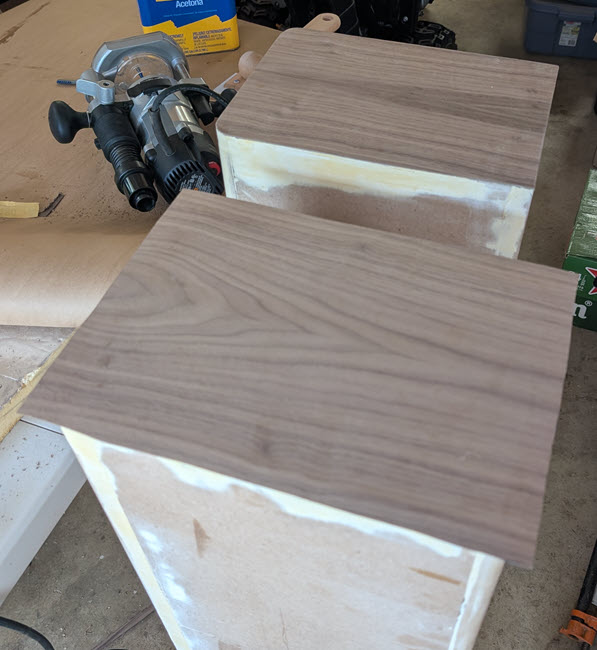
When this veneer didn’t bubble up but stayed put, I ordered a large sheet of quarter-sawn walnut veneer.  When I started, I didn’t consider that veneer is usually made up of pieces of wood that are five or six inches wide.  I think this is called slip matching.  The joints leave lines in the veneer about which the wood grain is mirrored.  I am picky and didn’t want the mirror lines to be offset from the center line of the cabinet front, so I had to offset my cuts of veneer, which in turn led to more waste and required me to get more veneer than I first thought.  If you are as new to veneering as I am, then it is important that you include this in your plans before ordering veneer.

I decided to apply the veneer to the bottoms first, then to the backs, then a big sheet that wrapped from one side across the front and over the other side.  I finished off with the tops.  This approach minimized the number of viewable seams where veneer panels met.  The fact that the veneer supplier used a dark paper medium also made the seams hard to see.  I used a flush-cut 1/4” router bit to trim the veneer to match the cabinets once the contact cement cured, as shown in figure 24.  Note that the seams where the veneer pieces join are centered on the cabinets.  Once the veneer is placed on the cabinet, it is pressed together using a veneer scraper, moving along the grain, never across it, to achieve maximum strength bond.  Most manufacturers recommend scraping the surface twice.  I used the centerline technique discussed on the www.veneersupplies.com website.

Figure 24: Veneering the Bottoms: Before and After Trimming the Edge.

Jon Peters, who authors Longview Woodworking on YouTube, noted that 
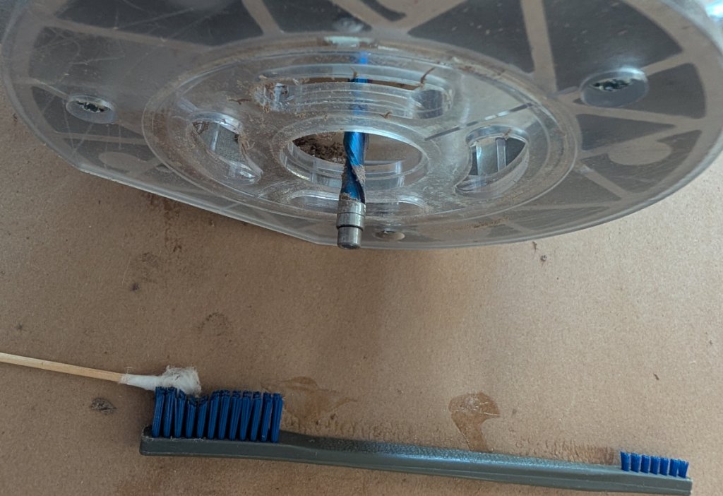
the flush cut bit in the router will often get caked with contact cement (as seen in figure 25) so periodically I'll clean the router off with WD-40.  I use a cordless router, so I just take the battery out when I'm doing something like that.  If it's a corded router, I would unplug it before cleaning off the router bit.  Before you put it onto your project, turn the router on and onto the side and let any WD-40 that might be in the bearing or something fling out so it doesn't get on your project.

<https://www.youtube.com/watch?v=Y8V3w0PUkYM&pp=ygUcRnVtZWQgRXVjYWx5cHR1cyB3b29kIHZlbmVlcg%3D%3D>

Figure 25 shows the contact-cement residue that I was getting when I trimmed the bottom veneer.  In my case I used acetone, cotton swabs, and a nylon brush to repeatedly clean the flush-cut bit while trimming the cured veneers, as seen in figure 26.

Figure 25: Trimming Veneer with Router Exposes Contact Cement.

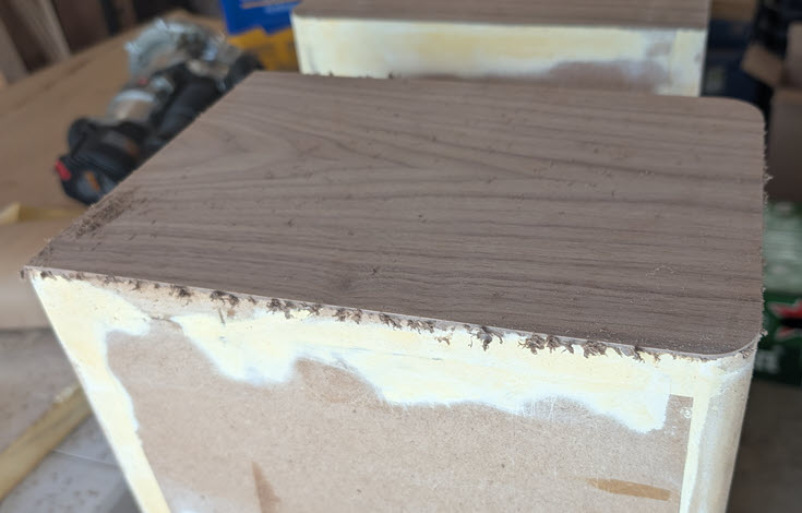
Figure 26: Cleaning Contact Cement from Router Flush-Cut Bit.

Jon Peters also said that when you use the flush cut and clean it up, you're often left with almost like a little bit of a film and that can be difficult to get off and if you don't do it the right way you can end up with a problem.  I always use 120 to 150 grit and you're going to sand kind of up along kind of like you're pushing that flap kind of up and kind of cutting it at the same time, and the reason why you wouldn't want to use a heavy grit paper is you could actually tear the fibers of the veneer off inside the surface of the finished piece so just be careful when you do it.  But it's something that does take some time it's one of those boring details that's kind of hard to get into on a project video but every one of my edges I have to I have to kind of carefully it's just like this kind of a motion you're kind of sanding it and then you're like I could do it like this and then you kind of cut it you know so it's all about just sort of taking your time and not screwing up your project again don't use anything coarser than 120 or 150: that should work as far as anything else.

Once I was happy with my veneering on the cabinet bottoms, I started on the cabinet backs.  The backs would hide the bottom edge, and the other veneer pieces would hide the other three back edges.  I haven’t yet said, but the MDF substrate and the paper backing of the veneer must be scuffed with 80-grit sandpaper to increase grip with the contact cement.  Figure 27 shows the backs of the cabinets with contact cement applied and dried enough to allow the veneer to be applied.  The cement looks splotchy, but it seemed to work.  When the contact cement is ready for adhesion, the finish should be shiny, not cloudy.  I think I overlapped some sections and caused the dull appearance.

Note that I used blue painters’ tape to mask places where I didn’t want contact cement to spill over.  This is especially important for surfaces that are already veneered, like the bottoms.  I learned that this tape should be removed once the cement sets and is ready for veneer.  If I wait 24 hours for the cement to cure, that masking tape is hard to remove!

Figure 27: Contact Cement on Back of Cabinets Ready for Veneer.

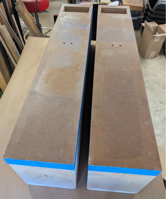
With the bottoms and backs veneered, it was time for the 800-pound gorilla.  I needed to apply contact cement to the back of a sheet of veneer that was 34” wide and 44” tall as quickly as I could, then apply the cement to the sides and front of a cabinet.  I cut at least two long sheets of construction paper to cover the table so I could apply cement to the veneer, then set the veneer aside and drop a second sheet of paper on the first to cover any contact cement that was there.  Then I could rest the cabinet on its back on top of spacers that allowed the excess veneer to hang above the table when applied.

My pickiness with centering veneer joints was aided by using a laser lever that was set up while the contact cement was drying to the point of applying the veneer.  I got close to the middle of the cabinet, and that has to be good enough because once the veneer “contacts,” it’s stuck.  The veneered result is shown in figure 28.

Figure 28: Veneer Wrapping Front and Both Sides.

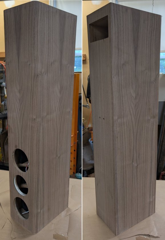
After I trimmed the edges with a router, cleaned the contact cement with a sanding block, and trimmed the driver and port holes with a router, I ended up with the cabinet shown in figure 29 that is standing on its head because that’s the last surface that wasn’t veneered yet.  It looked pretty good for a first veneer job.  The tweeter hole had a slight recess at its outer diameter that is too shallow for the flush-trim bit to trim: I had to cut the excess veneer over the recess away by hand.

Figure 29: Speaker Cabinet Veneered on Five Sides, Sitting on Its Top.

Adding Speaker Feet

Now that the cabinets were veneered, I added two sets of Dayton Audio DSS4-BK Black Speaker Spikes to the bottoms.  The instructions indicated that the spikes should be mounted 1-1/2” from all sides, but my cabinets are narrow, so I mounted them 7/8” from the sides as seen in figure 30.  The original speaker plans show an additional base that measures 14” by 15,” and I may need to add such a base if the cabinets are not stable when standing.  I guess I can bolt the base to the spike inserts!

Figure 30:Speaker Spike Inserts on Cabinet Bottom.