Purpose* This report documents the successful build of a pair of Signal Transfer Blameless Amplifiers, along with sharing construction hints, components sourcing, lessons learned and test results.
* The initial goal was to achieve a pair of high-fidelity amplifiers having moderate power rating 30W RMS per channel into 8-ohms.
Background* The inspiration for this project began with my purchase of Douglas Self's book
"Audio Power Amplifier Design", 6th edition (ISBN 978-0-240-52613-3), an extremely comprehensive reference book covering everything from design through testing and construction.
Finished Product* Front, rear and top views of the completed power amplifiers are shown in Figures 1, 2, 3 and 4, respectively.
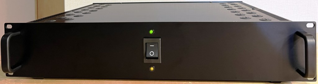 Figure 1. Front view - Yellow LED Power On, Green LED Loudspeaker Protection Enabled
 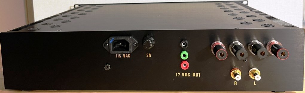 Figure 2. Rear view - IEC AC inlet, Fuse Holder, DC Power Out, Speaker Binding Posts, RCA Sockets.
 * The Black/Green/Red terminals on the rear panel supply +/- 17V DC for powering external/auxiliary equipment such as a preamp, electronic crossover etc.
* To facilitate loudspeaker bi-amping, two identical amplifiers were built, with the only difference being the selection of output power transistors. One amplifier was assembled using 2SA1295/2SC3264 MT-200 devices (Fig. 3), the other was assembled using MJ15024/MJ15025 TO-3 devices (Fig. 4). Audio sound quality from both amplifiers is excellent, as described later.
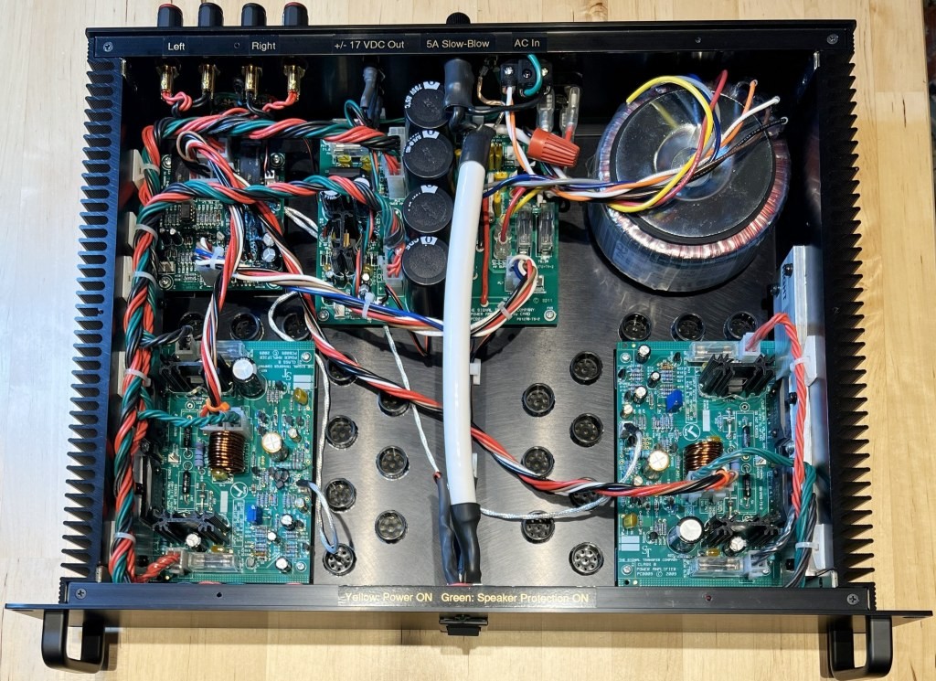 Figure 3. Top view of final assembly, amplifier fitted with 2SA1295/2SC3264 output transistors.
 * Shown clockwise from top left: Protection Board, Power Supply, Power Transformer, Right Channel, Left Channel.
* Output power transistors fastened with MT-200 insulating washers to aluminum bar, in turn fastened to integral side heatsinks.
 Figure 4. Top view of final assembly, amplifier fitted with MJ15024/MJ15025 output transistors.
 * Shown clockwise from top left: Protection Board, Power Supply, Power Transformer, Right Channel, Left Channel.
* Output power transistors fastened with TO-3 insulating washers to aluminum angle, in turn fastened to integral side heatsinks.
Major Components Sourcing/Alternatives* Printed Circuit Boards. This was a straightforward purchase order sent to The Signal Transfer UK for; 4 sets of Compact Blameless Class B Power Amplifier Boards (PCB009), 2 sets of Amplifier Power Supply Boards (PCB014), and 2 sets of Amplifier & Loudspeaker Protection Boards (PCB008).
* Metal Enclosure. Locally purchased 2 sets of Takachi model HYRH88-43-33BB, where HYRH denotes integral heatsinks including rack mounting and front handles, with overall dimensions 88 mm high, 430 mm wide, 330 mm deep. I chose BB, the colour Black.
* Power Transformer. Hammond 1182P22. 225VA, input 115V/230V AC, output 44V C.T. @ 5.11 Amps. Primary windings were connected for 115V operation for compatibility with the rest of my audio equipment rated 115V. That said, both amplifiers had no issues operating over the range of 100V AC to 120V AC using this exceptionally quiet toroid transformer.
* External Connectors. Although the Furutech connectors were expensive, their build quality is superb. IEC Inlet FI-06 NCF, Binding Posts FP-803(G), RCA Sockets FP-900(G).
* Electrolytic Capacitors. Power supply was first fitted with CDE 6800uF 63V, then upgraded to CDE 12000uF 63V (described later). Audio circuits have Nichicon Fine Gold series. Bypass and general-purpose capacitors are Nippon Chemicon SMG series.
* Ventilation Ports. Enclosure panels were drilled to fit vent plugs type Heyco 2657 and 2677.
* While a detailed parts list is provided with the purchase of each Signal Transfer board, the part numbers given were UK based stock codes which I could not source locally, nor could I find a cross-reference list. It took considerable time but finally completed a master list (Table 1) of the critical hardware parts, hard-to-source parts, and substitute parts where the originally specified part could not be found. With this list, it should be straightforward to provide these manufacturers' part numbers to your preferred supplier.
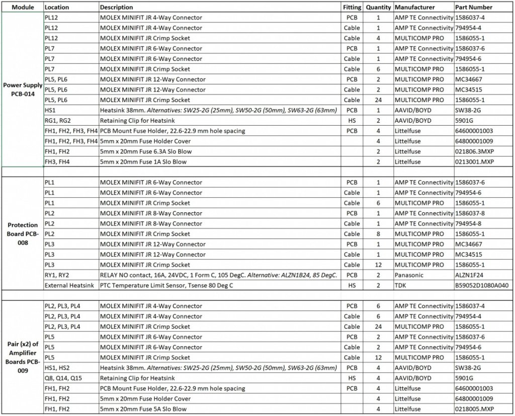 Table 1. Critical hardware components - listed by application, description, quantity, and manufacturers' part numbers.
 * The Molex 2-pin and 3-pin connectors are not listed in Table 1 as these small parts could be sourced locally (2-pin connector set: 5046 PCB Header & 5051 Cable Receptacle. 3-pin connector set: 5045 PCB Header & 5051 Cable Receptacle).
* The Molex Minifit connectors for PCB mounting are straightforward to install in their respective positions. However, when ordering the 4, 6, 8 and 12-way Molex connectors for cable/harness fitting, suggest ordering extra of these cable connectors should you need to modify the harness length or routing (as I had to do), or if there is a mistake (as I made!) when inserting the wrong wires in the cable sockets.
* The Molex crimp sockets 1586055-1 are supplied with qty 100 per reel. It's okay to have excess crimp sockets as extras are needed to remake any harnesses (as I had to). Should you need to rework a cable connector, there is a specialist tool "TE Connectivity 1586343-1" useful for extracting the crimp sockets, however for its price you can purchase a full set of replacement connectors.
* In my case, the most challenging component to source was the relays for the Protection Board. The recommended relay is a "GOODSKY GZ-SS-124L", where "SS" is flux proof, "1" is SPDT, "24" is 24V DC coil, and "L" indicates higher coil resistance (lower current draw). Unfortunately, I could not find a supplier for the GOODSKY relays, however with these specifications I located an equivalent from the Panasonic Automation Controls Catalog "ALZN1F24", a SPDT industrial relay where "1" indicates Form C type, "F" indicates Class F insulation 105 Deg C, and "24" the DC coil voltage. As I was unsure if this Panasonic relay would be suitable or not, I initially ordered just 1 as sample to try. Fortunately, this Panasonic relay was a perfect match, but when it came time to order the remaining 3 relays (2 are needed for each board), production had stopped during Covid and it was almost 2 years later before stock was replenished to reorder. Lesson learned, I ordered an extra 2 relays for spares, just in case.
* For the transistors and diodes, provided specifications are equivalent, there is considerable flexibility in sourcing alternatives. Although not an exclusive list, the transistor and diode alternatives successfully substituted for this build are listed in Table 2.
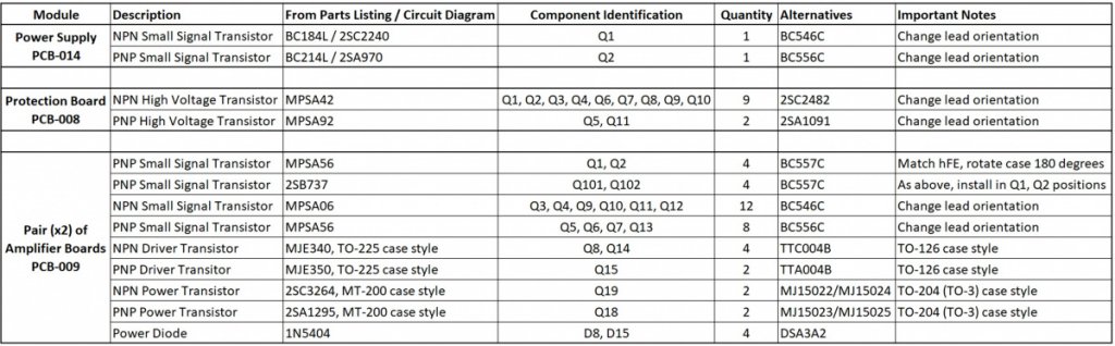 Table 2. Transistor/Diode alternatives - listed by part description, identification, quantity, alternatives, and important notes.
* For many of the small signal transistor alternatives, while electrical specifications matched, different form factors necessitated a change in the lead's orientation. In the case of Emitter-Base-Collector (E-B-C) orientation vs C-B-E, the transistor was simply rotated 180 degrees and fitted. However, in the case of E-B-C vs E-C-B orientation, it required the Base and Collector leads to be crossed over and insulated to prevent short circuiting. An example is shown in Figure 5.
* As mentioned, one amplifier was assembled using 2SA1295/2SC3264 MT-200 output devices, the other was assembled using MJ15024/MJ15025 TO-3 output devices. While the configurations and heat-sink mounting method is very different between these two, both types of power transistors performed exceptionally well, an endorsement of the flexibility of the Blameless Amplifier circuit design. Although not tried, other suitable power transistors should also work.
Construction and Testing - Power Supply* Initially the 4 large capacitors fitted were CDE 6800uF 63V and these worked well, then to further reduce power supply ripple these were replaced with larger CDE 12000uF 63V (Fig. 5).
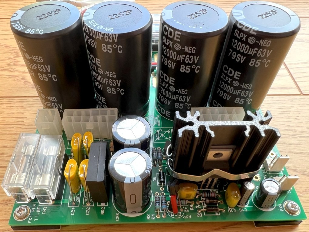 Figure 5. Completed Power Supply - note crossed Collector-Base leads to fit alternative transistor Q2.
 * Why were the power supply capacitors changed to larger capacity? The 6800uF capacitor's height of 40 mm and diameter 30 mm (maximum diameter that can be fitted on the PCB) were purchased before the enclosure type and PCB standoffs had been decided and concern was for sufficient clearance between top surface of the capacitors to underside of the top panel. But a check after fitting all components revealed there was just enough clearance to fit a larger size, hence the change to 12000uF of same diameter 30 mm but increased height 50mm.
* To confirm the reduction in power supply ripple a comparison test was conducted by inputting a 1 kHz signal to the amplifier while driving an 8-ohm load (Fig 6). Superimposed on the larger 100 Hz ripple can be seen the smaller 1 kHz signal.
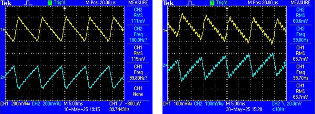 Figure 6. Capacitor comparison: 111-115mV RMS ripple using 4 of 6800 uF (left)
,
61-64mV RMS ripple using 4 of 12000uF (right).* The recommendation in the instructions is to fit capacitors of 10000 uF having 50V rating, and this is a good recommendation, whereas I fitted capacitors of 63V rating to allow for possible installation of a higher voltage power transformer in future. Although there was not much difference in price of these capacitors, suggest installing the largest capacitance that physically fits and is within your budget.
Construction and Testing - Protection Board* Much of my audio equipment, including the loudspeakers, is vintage and would be devastated by failure, hence would highly recommend including this (or other) protection circuit in any amplifier build.
* Apart from the long delay in procuring the relays, assembly of the protection board was straightforward. For some reason I received both a version 4 and a version 5 of PCB008, however the only difference being the addition of a 150k ohm resistor R34 across C3 - this was easily fitted to the underside of version 4 PCB (Fig. 7).
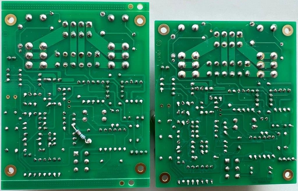 Figure 7. Assembled protection boards PCB008 - version 4 with added 150k ohm resistor (left)
,
version 5 (right).* To confirm proper functioning of the PTC Temperature Limit Sensors for over-temperature protection, a thermocouple was sandwiched between two of the temperature sensors, while slowly increasing temperature with a heat gun (not shown). At room temperature the limit sensors exhibited low internal resistance, then at approx. 84 Deg C the internal resistance rapidly increased (Fig. 8).
 Figure 8. Resistance measurement of Temperature Sensors at room temperature (left), at resistance change (right).
* To confirm proper functioning of the DC Detect Shutdown, a small battery pack was connected and then disconnected at the speaker output pins. Tested at first with +6V DC (Fig. 9), then test was repeated with -6V DC (not shown).
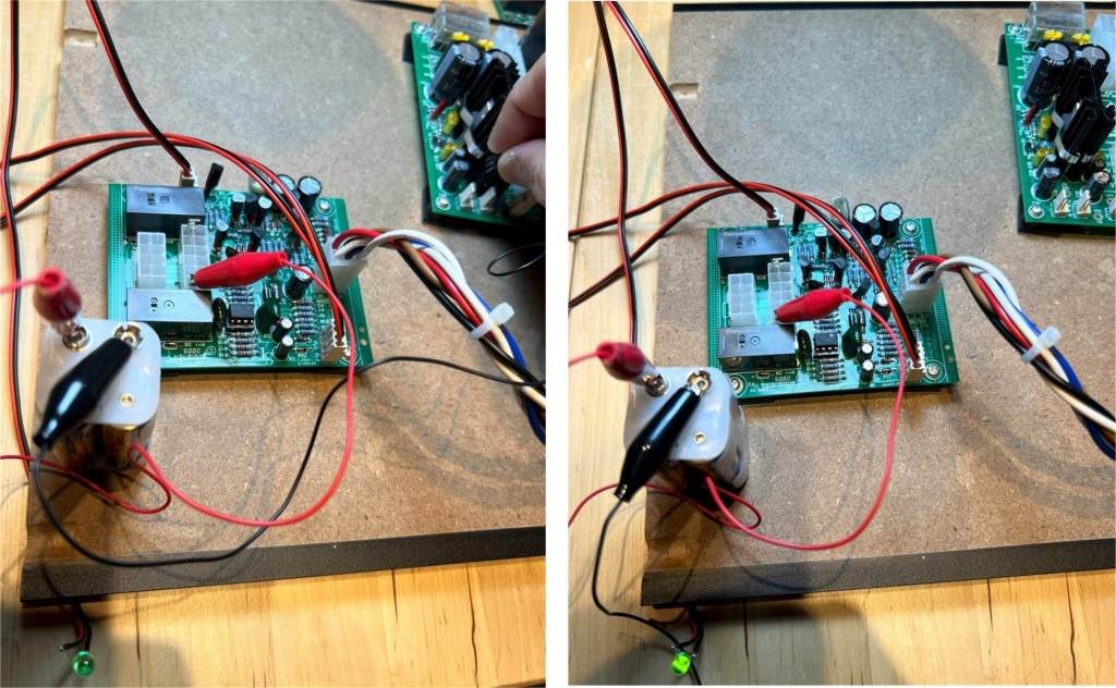 Figure 9. With +6V DC applied protection relays open and LED turns off (left), DC voltage removed protection relays close and LED illuminates (right).Construction and Testing - Enclosure
* Machining the metal pieces by hand was a lengthy task. Having only a portable electric drill to drill the several holes for the ventilation plugs was one thing, but cutting a rectangular hole for the power switch and a trapezoidal hole for the IEC inlet was another thing. Thankfully, the final result turned out okay.
* Although it wasn't even audible, I investigated how to reduce noise pickups, 50/100 Hz AC induced and some random 17-18 kHz noise. Recently I purchased a QuantAsylum QA403 Audio Analyzer and this instrument greatly helped in identifying potential sources of noise and the effectiveness of reducing these noises.
* To reduce the 50/100 Hz peaks, each of the following contributed a small individual improvement, for a combined improvement of approx. 3 dB reduction (increasing negative dB number).
a) Optimum rotation of the toroid power transformer.
b) Replacing the internal AC power line with 2-conductor shielded cable (Fig. 3 and 4, the large white cable in centre).
c) Close spacing of the RCA sockets to minimize external ground loops (Fig. 10).
d)Use of central earth ground and careful routing of shielded cables and ground connections.
* To suppress any potential high-frequency noise, a single 1nF ceramic condenser (small blue object visible at the terminal lug, Fig. 10) was connected between the RCA socket shields and the enclosure chassis.
 Figure 10. Back panel sub-assembly, left to right - Binding posts, RCA sockets and shielded cables, 17V DC lines, Fuse holder, Earth Ground, IEC Inlet, Main Bridge Rectifier.
 * Another problem that occurred was elevated temperature in the power transistors. At times the output devices were warm to touch, but at other times some of the power transistors, not all of them, were very hot. Considering the massive heat sinks with this enclosure this was concerning. As a precaution against high internal temperatures, holes were drilled in the top and bottom panels to fit multiple ventilation plugs Heyco 2657 plugs in top panel, and larger Heyco 2677 plugs in bottom panel (Fig. 1, 2, 3, 4). Much later I discovered the cause of over-heating was an instability within the bias current setup, this is described later and thankfully remedied.
Construction and Testing - Amplifier Boards* Assembly of the amplifier boards was straightforward.
* The only discrepancy, albeit minor, concerned the value of ceramic condenser C16 shown as 68pF in the PCB008 circuit diagram, whereas I followed the parts list where it's listed as 100pF, and 100pF is the value installed in both boards. Unsure if 68pF or 100pF makes a difference, consulting the book "Audio Power Amplifier Design", chapter 13 section "Stability and VAS Collector-to-ground Capacitance" it explains the purpose of this capacitor is to suppress parasitic oscillations in the output stage.
* Why build two identical amplifiers having two different sets of output transistors? It's a good question as the transistor mounting and heatsink attaching is very different between the two assemblies. As documented in report "Bryston 2B Power Amplifier repair - Hints and Lessons Learned"
https://www.audiocircle.com/index.php?topic=184949.0, the power transistors in the left channel of this vintage amplifier had failed and to repair this I purchased new MJ15024/MJ15025 power transistors having the same TO-3 case style. As I had no idea whether this repair would be effective, or if the right channel might suffer the same fate, I ordered extras of the MJ15024/MJ15025 power transistors as spares. As it turned out the single set of MJ15024/MJ15025 power transistors successfully repaired the Bryston 2B amplifier, and that explains the use of these available power transistors in the Blameless Amplifier build. For the 2SA1295/2SC3264 amplifier build I was curious how these devices might perform, and as I could locally purchase a pair of original Sanken units including the MT-200 insulating washers for Yen 1100 (about $7.50 at current exchange rate) it was not expensive. A plus point from this exercise, it shows with the Blameless design there is freedom to choose a preferred power transistor type and heatsink configuration.
* The TO-3 devices with silicon insulating washers were mounted on a section of 2mm x 40mm x 40mm aluminum angle, with short fly leads connecting the transistor terminals to the PCB (Fig. 11, 12). For securing the angle sections to the side heatsinks, each heatsink was drilled and threaded to accept M3 fastening screws.
* The MT-200 devices with mica insulating washers were fastened to a section of 6mm x 40mm aluminum bar, with the underside of the bar drilled and threaded to accept M2.6 fastening screws from the PCB (the recommended M2.5 hardware is not commercially available in Japan). For securing the bar sections to the side heatsinks, each heatsink was drilled and threaded to accept M4 fastening screws (Fig. 13).
* Both amplifiers used the same TTA004B and TTC004B driver transistors and these performed splendidly. Side comment, silicon washers were used to insulate the plastic TO-126 cases from their heatsinks, but at the voltage levels within this amplifier and with insulated plastic TO-126 cases the silicon washers could have been omitted.
* In the instructions provided there are helpful recommendations to perform visual inspections and safe power-up, such as use of a Variac to gradually increase the supply voltage, testing under no-load etc. In lieu of a Variac I was fortunate to have access to a dual-voltage variable power supply and indeed the amplifier board comes alive starting from about +/- 3V DC supply. Another precaution I used was to test the amplifier without load before connecting the output power transistors.
* For the input differential pairs, PNP transistors 2SB737 were installed in positions Q101 and Q102. By swapping around these transistors, very low offset voltages could be achieved at the speaker outputs typically between 1mV and 11mV, except for one pair where the measured offset voltage was higher at approx. 26mV. For this one pair only, I swapped out the two 2SB737 transistors for a matched pair of BC557C transistors which brought the offset voltage down to 1mV (Table 3). Of course, this required the BC557C transistors to be installed in the alternate positions Q1 and Q2, but it's a nice feature with PCB009 it accommodates either transistor configuration.
* Once fully assembled, final testing of this amplifier under full load exceeded my expectations. Test setup included a Function Generator App on iPad to provide a 1 kHz test signal, a set of heat-sinked ARCOL power resistors to provide 4-ohm and 8-ohm loads, and digital oscilloscope to capture the waveforms and record maximum RMS output voltage before clipping (Fig. 11, 12, 13, 14).
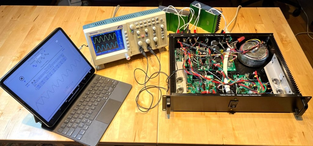 Figure 11. Testing the MJ15024/MJ15025 amplifier under 8-ohm load - single 8-ohm load resistor connected.
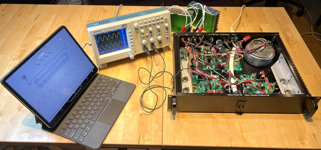 Figure 12. Testing the MJ15024/MJ15025 amplifier under 4-ohm load - twin 8-ohm load resistors parallel connected.
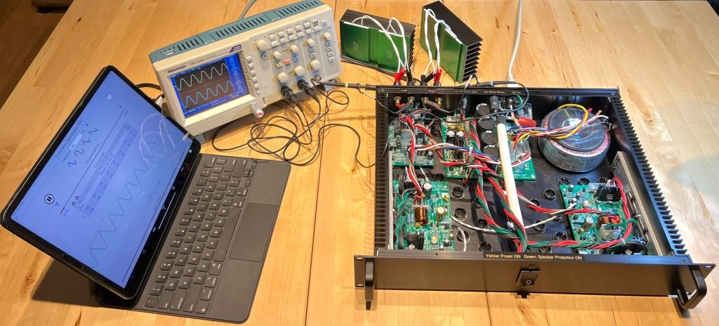 Figure 13. Testing the 2SA1295/2SC3264 amplifier under 4-ohm load - twin 8-ohm load resistors parallel connected.
* Examples of maximum signal output before clipping, for both channels driving 8-ohm and 4-ohm loads are displayed in Figure 14.
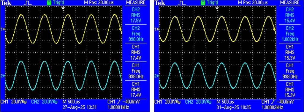 Figure 14. Maximum amplitude waveforms measured with 8-ohm load (left) and 4-ohm load (right).
* Examples of RMS power calculations derived from Figure 14.
a) For 8-ohm load: (17.4V RMS)2 / 8 ohms = 37W RMS per channel.
b) For 4-ohm load: (15.3V RMS)2 / 4 ohms = 58W RMS per channel.
* As mentioned previously, a problem that often occurred was elevated temperature in the power transistors. At times the output devices were warm to touch, but at other times some of the power transistors, not all of them, were very hot. Considering the massive heatsinks in this enclosure this was concerning. Eventually what I determined was the bias mechanism that regulates the quiescent current in the output devices was unstable. Two causes:
1) CFP output resistors. These resistors are specified in the parts list as wire-wound 0.1-ohms, tolerance not given. Not sure why, but at the time of parts procurement 0.1-ohms wire-wound was not available, instead 0.1-ohms metal-oxide film, 5% tolerance resistors (Fig. 15 left) were available and installed. Measuring the in-circuit voltage drop individually across these resistors showed an imbalance, possibly related to the 5% tolerance. These resistors were then replaced with special order for wire-wound 0.1-ohms, 1% resistors, which cured the voltage imbalance issue.
2) Single-turn bias potentiometers, 1kohm (Fig. 15 left). This is a delicate adjustment, with just a quarter turn it could change the quiescent current from hard-off to full-on, furthermore there was hysteresis in the positions, that is rotating in one direction gave a different result from rotating in the other direction. I tried two different types (Fig. 15 left), but same issue with both. The single-turn potentiometers were replaced by multi-turn potentiometers of same value 1kohm, which gave much needed finer control of the quiescent current level. Fitting the multi-turn potentiometers required careful bending of the leads to fit, but it's working well (Fig. 15 right).
* Desoldered from two of the amplifier boards are the metal-oxide film resistors and two types of single turn potentiometers, alongside one of the modified amplifier boards (Fig. 15).
* Now that the power transistors remain thermally stable, I have not witnessed any elevated temperatures regardless of operating conditions.
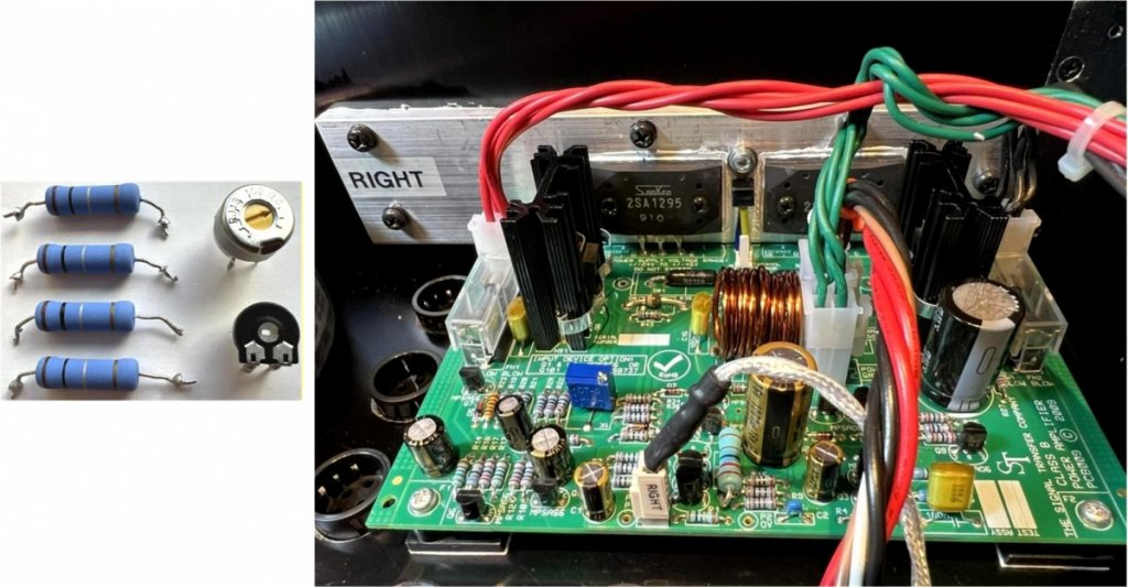 Figure 15. Original resistors & single-turn pots (left), modified board with multi-turn pot (colour blue) and wire-wound resistors in front of power transistors (right).
 * With the quiescent current now stable, the bias voltage was adjusted to minimize distortion at 250mW for both channels, paying attention not to set the bias level too high risking elevated temperatures. Further refinement may have been possible by adjusting the bias at other power levels, but I felt 250mW was a reasonable place to start.
* Final bias voltage: Measured across the two output resistors (0.1 + 0.1 ohms), power on for 2 hours, inputs shorted.
* Final output offset voltage: Measured at binding posts, power on for 2 hours, inputs shorted, no-load connection.
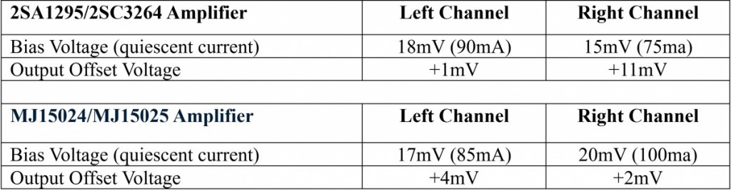 Table 3. Final measured values for Output Offset Voltage and Bias Voltage for the two amplifiers.
 * With the bias voltage fixed, power was then increased to +30W for both channels and the corresponding total harmonic distortion (THD) measured.
* Using my recently purchased QA403 Audio Analyzer, the amplifier's performance was measured using the setup shown in Figures 16 and 17. While not the professional Audio Precision audio analyzer instrument referenced in the book "Audio Power Amplifier Design", for a hobbyist the lower cost QA403 is ideal.
* The QA403 has differential inputs and outputs and can be susceptible to external noise from cables. Constructing a pseudo-balanced cable configuration, while far from perfect, provided better noise immunity with the amplifier's single-ended inputs.
1) QA403 outputs connected to amplifier inputs with close-spaced coax cables.
2) QA403 inputs connected to amplifier outputs with close-spaced shielded twisted-pair cables. Note shields connected only at BNC inputs.
3) Amplifier chassis, load resistors with heat sink connected to common ground at QA403 chassis.
4) RMS Power: QA403 Audio Analyzer providing 1 kHz input signal with amplifier output measured at binding posts upstream of 8-ohm load. For each power level setting, data was acquired over full 1-minute durations.
5) Stereo measurement: Left and Right channels driven simultaneously, results listed in blue shading in Table 4.
6) Monaural measurement: For reference, an auxiliary test was made for one channel only (other channel input shorted to ground), example listed in yellow shading in Table 4.
 Figure 16. QA403 Audio Analyzer connections to amplifier under test - single-ended coax cabling with shielded twisted-pair cabling.
* For simplicity Fig. 16 does not show the load resistors and grounding connections. The left and right coax cables should be bound close together, likewise the shielded twisted-pair cables should be bound close together.
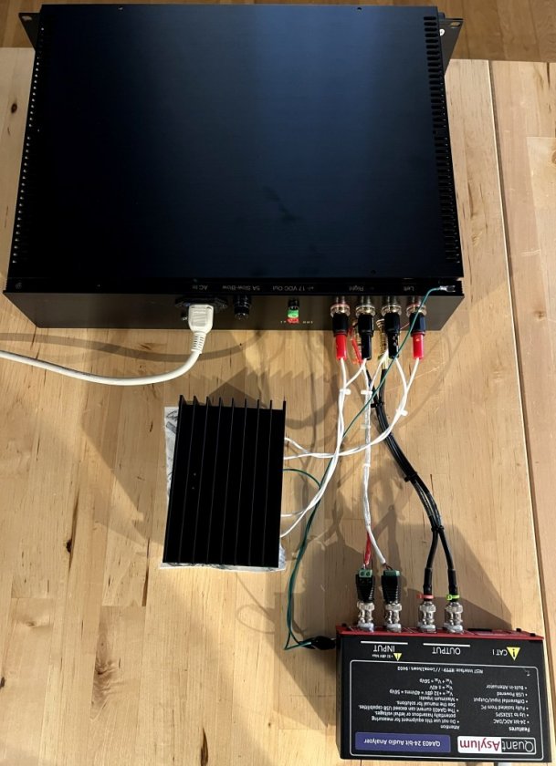 Figure 17. QA403 Audio Analyzer with pseudo-balanced and coax cable connections - amplifier loaded with heatsinked twin Arcol 8-ohm, 100W resistors.
 * To remove excessive heat at higher power levels, a gel pack can be seen placed underneath the load resistors heatsink. Using this refrigerated gel pack minimized load resistance changes from temperature changes.
* Taken together, the following three steps brought the background noise level down to ~ 1.3uV RMS, measured while acquiring QA403 data with the amplifier power off (Fig. 18).
a) L+R shielded twisted-pair cables bundled close together, likewise L+R coax cables bundled close together.
b) Green grounding wires connected from amplifier chassis and load resistor heatsink back to a common ground on the QA403 chassis.
c) A 0.6m length USB cable for high-end audio applications (Furutech GT2Pro-B, not shown) enabled the Q403 to run off the full 5V supply from the laptop PC battery, eliminating noise contamination from the AC adapter.
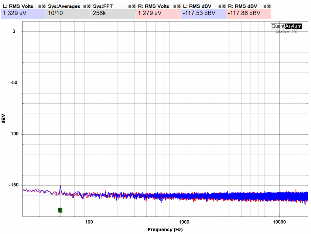 Figure 18. Background noise measurement with the setup in Fig. 17 - QA403 data acquired with amplifier power off.
 * Total Harmonic Distortion (THD) measurements were acquired at increasing levels of output power (Table 4).
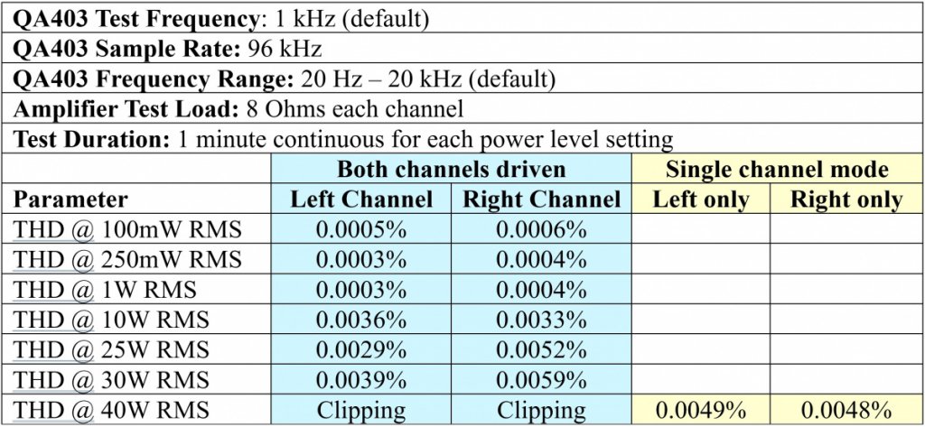 Table 4. Using QA403 to measure Output Offset Voltage and Bias Voltage of the 2SA1295/2SC3264 amplifier (similar results for the MJ15024/MJ15025 amplifier).
* When tested in single channel mode it demonstrated an increase in maximum available power, for example 40W RMS could be obtained from a single channel (Table 4, yellow shading).
* As my objective with this build was to achieve a pair of high-fidelity amplifiers having moderate power rating 30W RMS per channel into 8-ohms this objective was met, I am pleased with how things turned out.
* Although unlikely to influence the already outstanding sound quality, these measured THD values could potentially be reduced further by:
a) Increasing the bias level, but at risk of the output devices running hot. What I observed was that when the bias voltage approached 25mV (125mA) the output devices heated up rapidly. With the present settings (Table 3), I have not witnessed any abnormal temperatures, whether idling or driven at full output.
b) Improved interconnect cables. As mentioned, the QA403 has differential inputs and outputs and can be susceptible to external noise from cables. The noise-immunity of my homemade pseudo-balanced cables could be improved by experimenting with better configurations.
c) Other test equipment. A professional audio analyzer that supports single ended connections would connect directly with the amplifier eliminating the pseudo-balanced cabling.
Audio Listening* A tough test was to try the amplifiers with my Acoustat electrostatic speakers as these speakers have a complex impedance profile. According to the literature, it's recommended Acoustat speakers be paired only with high-power amplifiers capable of driving 2-ohm loads. I was astonished that these Blameless amplifiers with moderate power easily drive the electrostatic speakers with no degradation in sound quality. Impressive.
Future Considerations* If I was to start again or build another Blameless amplifier, what might I do differently? As my objectives were met and I'm pleased with the result there's nothing that needs changing, but here's a few thoughts.
* A higher power output, if desired, could be achieved by changing the Hammond toroid transformer 1182P22 (225VA, 44V C.T. @ 5.11A) to Hammond 1182S24 (500 VA, 48V C.T @ 10.42A).
* Based on the single channel test documented in Table 4, higher performance can be achieved by adding a second PCB014 power supply and transformer, i.e. a dedicated power supply for each channel, like a pair of monaural amplifiers.
* With the output device's temperature now under control the enclosure would not need so many ventilation plugs.
* Professional engraving for the enclosure's markings would be a nice touch; this work would need to be planned for and scheduled before assembly.
References*
"Audio Power Amplifier Design" (ISBN 978-0-240-52613-3).
http://www.douglas-self.com/ampins/books/apad.htm* The Signal Transfer Company for PCBs.
http://www.signaltransfer.freeuk.com/* Hammond Toroid Power Transformers.
https://www.hammfg.com/electronics/transformers/power/1182* Takachi HYRH series, Heatsink Rack Mounting Enclosure with Handles.
https://www.takachi-enclosure.com/products/HYRH* MJ15024 / MJ15025 power transistors described in report "
Bryston 2B Power Amplifier repair - Hints and Lessons Learned"
https://www.audiocircle.com/index.php?topic=184949.0


