Hi Groovecontrol,
You apparently have the same vintage (
1993) Amp as the one (of he two)
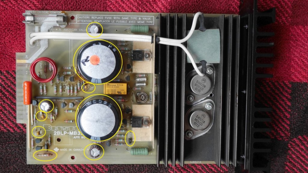
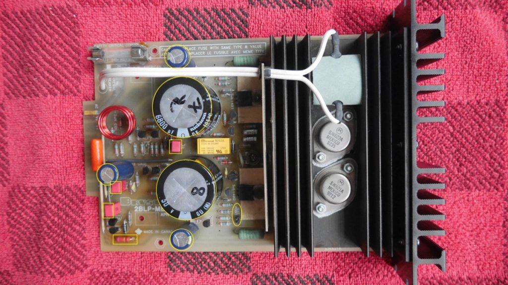
Serial #207634, which I recapped (Photo 1 and 2).
I judge this from the PCB Marking (
April 90) and the
Black ROE EYF 4700uF 50V 105 deg. C power rail caps.
(My other Bryston 2-LP (
1991),
Serial #205958, has
Gold coloured ROE's, same form factor, but is otherwise identical to the newer amp.
You have the professional version, which has a volume control, bot otherwise the PCB is identical.
1)
I did NOT touch the Bias setting, because this is
NOT required if you haven't replaced the SJ6521A /SJ 6522A Power transistors and/or the drivers (SJ1490/1491).
When recapping a fully working Bryston 2B-LP amp (as in my case), you do NOT have to reset the bias (leave well alone!).
2)
Also, I did NOT replace the dodgey bias pot by a multiturn Cermet pot.
(I would have done this, if I was repairing a blown amp).
If you do not touch the old pot, I think it will hold on, but if you are planning to readjust the bias, it is almost imperative to replace it.
If the wiper of the old pot opens up temporarily whilst adjusting, you will blow your power transistors.
3)
If you would replace this bias pot I would advise to first determine the setting by measuring (with an Ohm meter), the resistance between the wiper and each of the ends.
Next, I would reset the new (multiturn cermet) pot such that it hase the same reading between the wiper and the ends.
4)
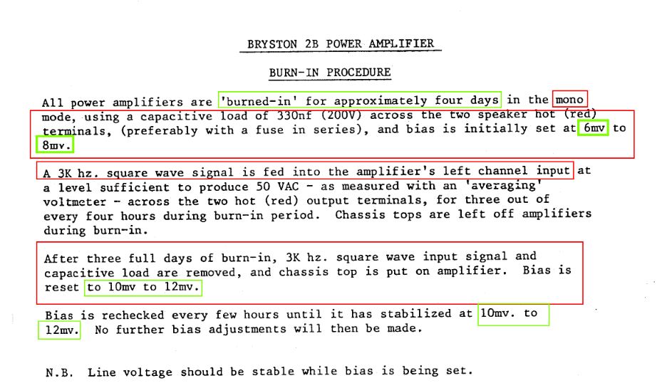
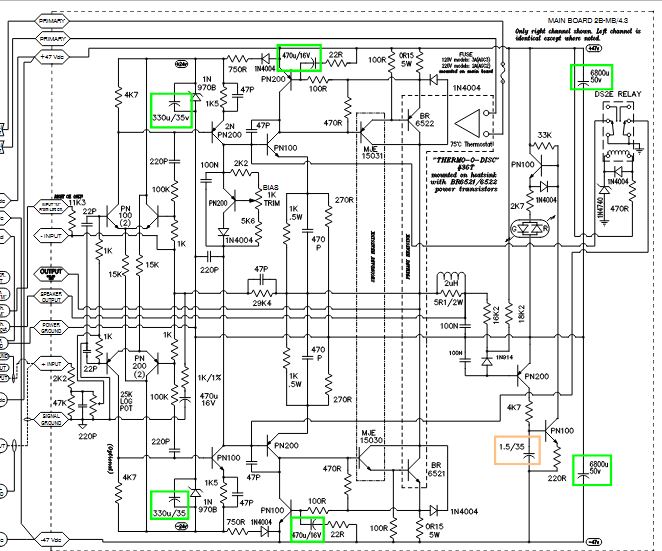
The procedure for setting the Bias is explained in Bryston's service sheet for the older (but almost electrically identical) Bryston 2B.
See attachment 3 for the procedure and attachment 4 for the correct schematic.
This file used to be on their website, but I cannot locate it anymore (I assume it is public though).
John Tullet has alaso provided a very detailed narrative on setting the Bias on a Bryston 2B :
https://www.audiocircle.com/index.php?topic=184949.msg1940311#msg19403115) Recommended Bias setting
The recommended bias setting (aged components and temperature stabilised) is
10 - 12 mV, measured across the
green 0.15 Ohm power resistor next to TP1.I would advise to make
dedicated plug + wires (which fit on
TP1) and hook up these wires to your DMM (in mV setting DC).
6) "Recapping"
Imperative:
2X
ROE EYF 4700uF 50V 105 deg C by
Nichicon 6800 uF 50V 105 deg C (Diameter 35m Height 32 mm).
Resistor for LED :
2K7 1/2W to be replaced by
2K7 3W Metal Film resistor : Your one is already partially fried!!
Optional:
3X
Chemiccon KME 470 uF 16V 105 deg.C by Nichicon UKA 470 uF 35V 105 deg C or Panasonic FC 470 uF 35V 105 deg C
3x
Tantalum KEMET 1.5 uF 35V by film capacitor WIMA MKS2 1.5 uF 63V
The tantalum caps have 50% safety factor (35V vs 24V rail voltage), but KEMET nowaday prescribes much higher safety factors : 2-3 Times the rail voltage!!
I replaced these tantalums , just to be sure!
The Nichicon's ( 470uF 16V) were still OK, the ROE's (4700 uF 50V) were definitely failing (bulged) and will then leak out a nasty electrolyte.
I hope that this has answered you questions.
I like these little amps and I am very happy with them and Bryston's excellent service.