Purpose* The purpose of this report is to summarize the successful installation of an MK3 kit in a ReVox B710 early series MK1 tape deck, and to share my experiences and hints with this installation.
History* I purchased this B710 MK1 new, serial number 003055 in February 1982 - where did 43 years go?
* Factory approved updates were implemented by Studer ReVox in February 1992, bringing this unit closer to MK2 status, although the basic structure remains as an MK1 configuration.
* A complete restoration including optimization of the Wow & Flutter is documented in report, "
ReVox B710 Tape Deck - Successful Wow & Flutter Restoration".
https://www.audiocircle.com/index.php?topic=190279.0 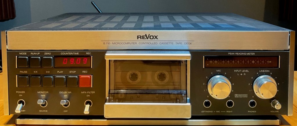 Figure 1. B710 MK1 modified with MK3 kit - shown in standby mode with clock display synchronized to NTP local time, 9:09 AM. MK3 kit components
* The MK3 kit is a functionality and operational enhancement suitable for all ReVox MK1 and MK2 cassette tape decks, the kit is sold and supported by ReVox.name. Full description is available here.
https://www.revox.name/sell/b710mk3/* Figure 2 shows the main components provided in the MK3 kit.
* Note the black lead terminated with connector lug carries the Monitor signal for the MK2 series, however my unit being an early MK1 series required modifying this termination, described later.
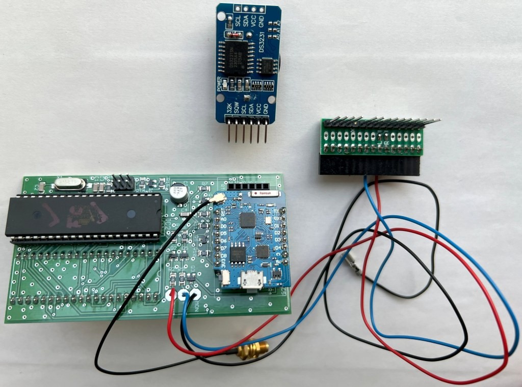 Figure 2. Clockwise from top: Battery/Memory board, Intermediate multi-pin connector, microprocessor board (x2 of 20-pin strips and Wi-Fi antenna not shown).
* If the original microprocessor chip is fitted directly on the microprocessor board, an optional 40-pin socket allows retrofitting of the original microprocessor chip (Fig. 3).
* In my case though, this early MK1 series was fitted with a piggy-back board for the microprocessor and hence this optional 40-pin socket was not required.
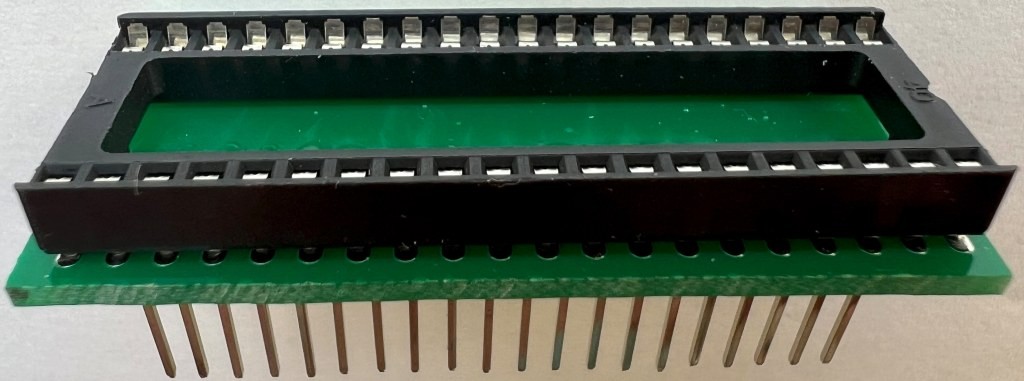 Figure 3. Optional 40-pin socket for retrofitting the original microprocessor chip directly on the microprocessor board.Installation of MK3 kit
* Installing the MK3 kit is straightforward following the instructions provided.
* To assist other first-time users with the installation of this kit, I contributed several suggestions to improve the readability of an earlier version of installation instructions. Pleased these suggestions have been taken onboard at ReVox.name, and are now included in the current version of instructions posted online at
https://www.revox.name/sell/b710mk3/#manual * In this report are recommendations and user hints captured from my experience of installing the MK3 kit in an early series of B710 K1 unit.
Removing the original microprocessor * I used a desoldering vacuum gun set to 330 Deg C to quickly and safely desolder all 40 pins. Extreme care must be taken during desoldering as the ReVox printed circuit boards have thin traces and are susceptible to delamination. In fact, there was a pad delamination at microprocessor pin #3 (Fig. 4).
* In hindsight, it may have been safer to have used a lower desoldering temperature, say 300 Deg C. But I was lucky as pin #3 is an NC (no connection) and fortunately no impact.
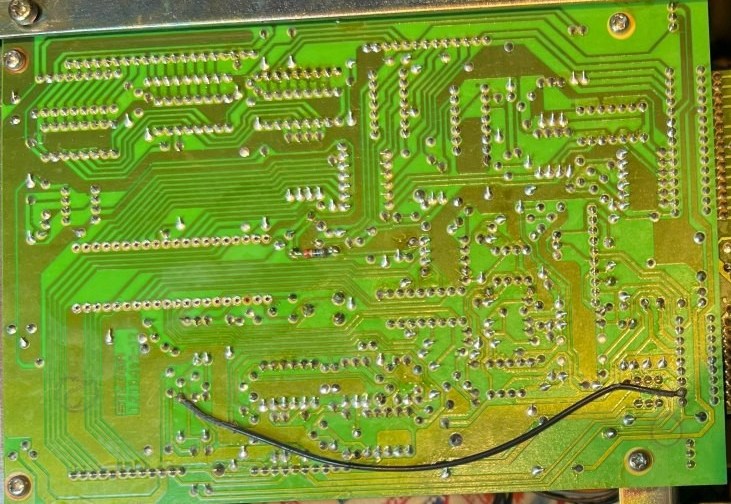 Figure 4. Early MK1 series microprocessor underside of board showing 40-pin chip removed - note pad delamination at pin 3.
 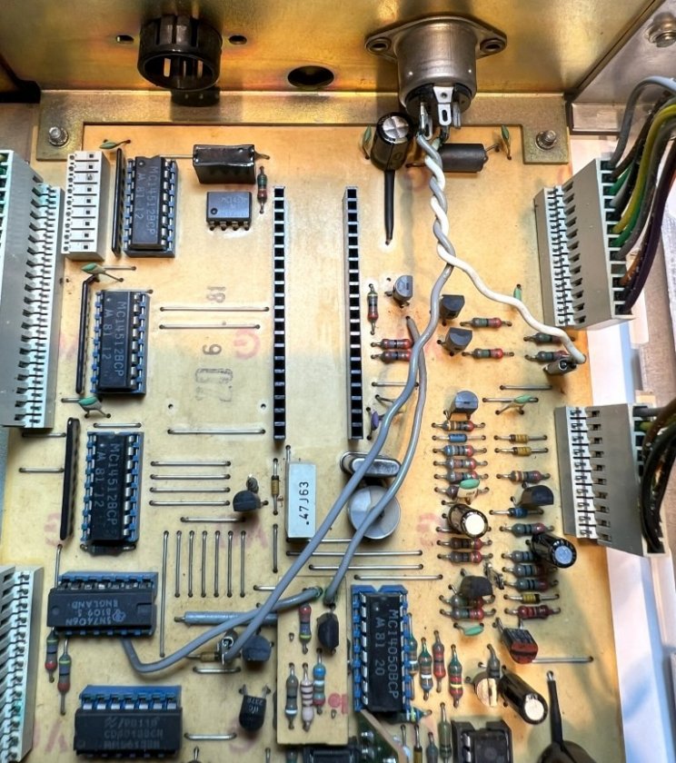 Figure 5. Early MK1 series microprocessor board with the new twin 20-pin strips installed.
* As a precaution, I confirmed the original microprocessor piggyback board could be inserted into the newly installed 20-pin strips (Fig. 6), should the need arise to revert to the original configuration and operation. An operational check then proved the B710 original operation and performance was indeed retained, including the critical back tension remaining within specification (measured stable 200mV voltage drop across resistor R27, as described in the B710 service instructions).
* The white/grey twisted pair shown in Figures 5 and 6 is for the Remote-Control power and could be removed, although I left it in place as is.
* The yellow wire shown in Figure 6 is only relevant to the original piggyback board and is not used with the MK3 kit.
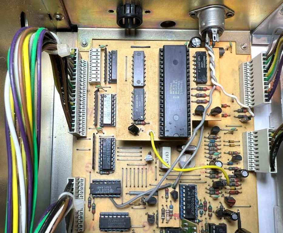 Figure 6. For reference, early MK1 series original microprocessor piggyback board installed in the two 20-pin strips.
* While the MK3 installation instructions explain how to connect the microprocessor's Monitor lead to the Audio Logic board with the MK2 and later MK1 series, my unit being an early series MK1 did not have the optional plug-in fitted (Fig. 7); so, a separate board header and cable receptacle were assembled.
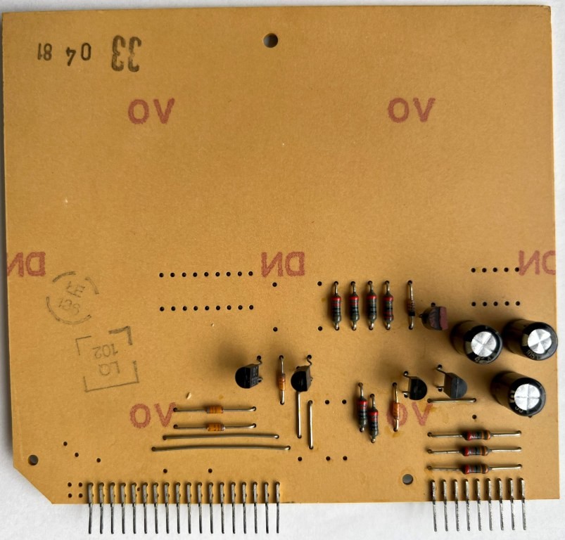 Figure 7. Component side of early MK1 series Audio Logic board.
 * I used Molex 3-position header/receptacle parts left over from another project (Fig. 8), although other types of suitable header/receptacle parts can be used.
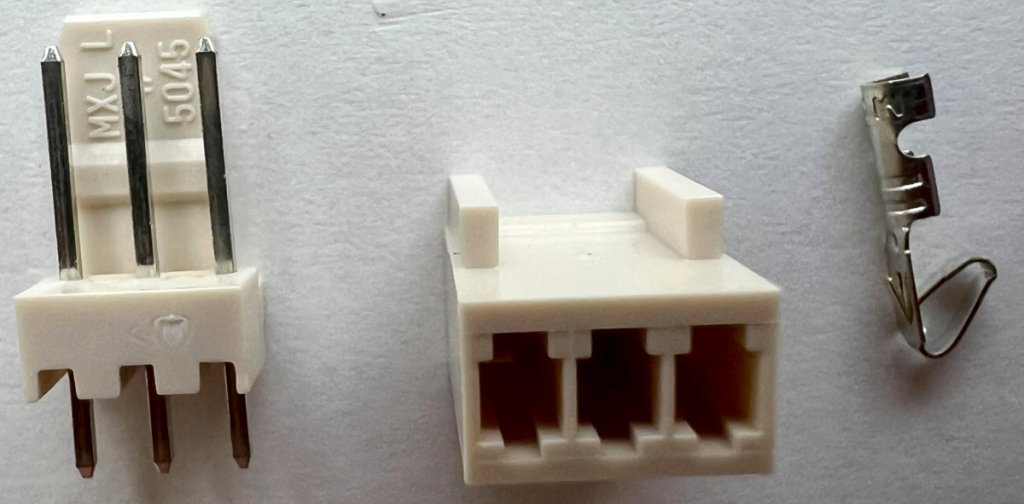 Figure 8. Molex 3-position connector set - 5045 PCB Header (left), 5051 Cable Receptacle (middle), Contact Pin (right).
 * View of assembly and connection of Monitor cable to Audio Logic board (Fig. 9).
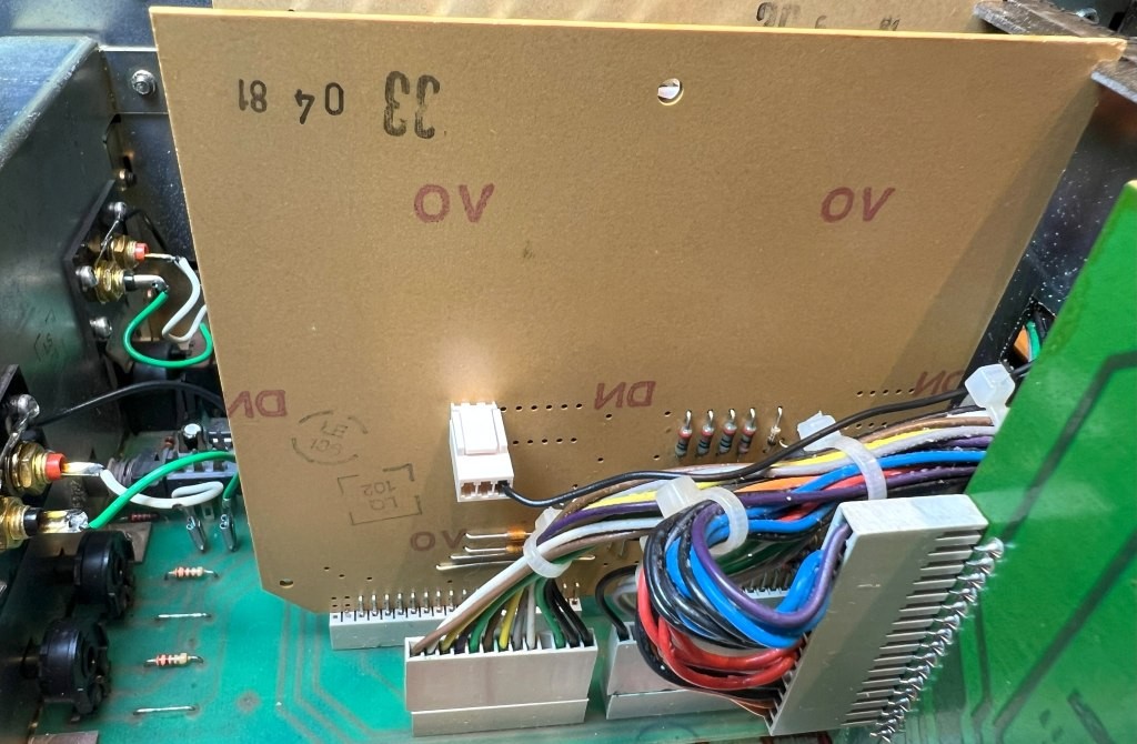 Figure 9. Monitor cable connected to early series Audio Logic board using Molex 3-position connector set.Adjusting the light barriers
* ReVox B710 service instructions section 3.5.2 provides an example of light barrier results, presumably obtained with new devices during manufacture (Fig. 10).
Safety! * Before proceeding with these tests, be careful and respectful at all times of internal mains voltages, present even when the unit is turned off and in standby.
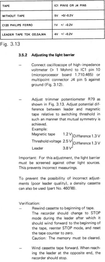 Figure 10. From ReVox B710 service instructions, section 3.5.2.
* If the tape deck passes the final Verification checks described in section 3.5.2 and functions properly, likely no adjustment of the light barrier is needed.
* The following tests were conducted on my early B710 MK1 series, where the light barrier set points had shifted over time.
Hints* If not already done so, before performing this test, check that the original 1k ohm R79 trimmer potentiometer has been replaced with a modern closed-face type. With the old open-faced trimmer, dust entry and corrosion will give erratic results. Before removing the old trimmer, mark its wiper position with a felt pen (in case of mistake with installation with the new trimmer). After removing, measure and write down its resistance setting, then set the new trimmer to this value.
* It can be difficult to attach a voltmeter test lead to IC1 pin 10, or to connector J4 pin 5. If the MK2 trimmers R4 and R5 are fitted, a more accessible and easier method is to connect a voltmeter test lead to the 1k ohm resistor R3 on the Head Lifting board (Fig. 11).
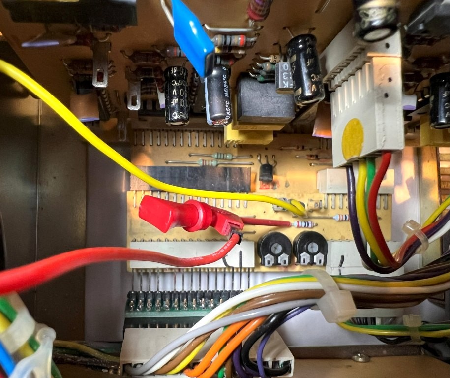 Figure 11: Test lead connected to R3 on Head Lifting Board (corresponds to Line #5 on P1/J4).
 * From the B710 service instructions section 3.5.2, achieving a 5V measurement "Without Tape" and a 2.5V value of "Threshold voltage" (presumed calculated from one-half of 5V) was not possible with this early MK1 unit. Instead, a series of tests were conducted using a Maxwell UR60 new tape at different rotational settings of the R79 trimmer potentiometer, until mutual symmetry was achieved in final test #5 (Table 1).
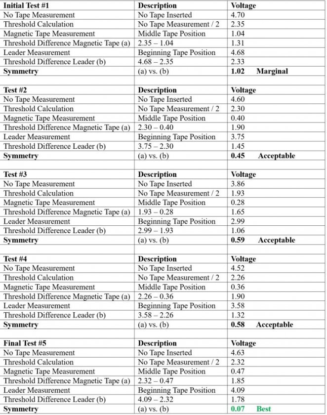 Table 1: Light barrier measurements vs. R79 settings - all tests performed with a Maxell UR60 new tape.Remarks
* Caution. As Back Tension has not been optimized at this stage, it's better to use a blank tape for these tests.
* Depending on age and condition, results obtained with other B710 tape decks will be different from these results.
* The adjustment of R79 was not critical, while achieving optimum symmetry is ideal, the symmetry results labelled "Acceptable" in Table 1 also worked for my unit.
Adjusting the light barrier's signal balance * The MK3 instructions recommend adjusting the signals of the light barriers by touching an oscilloscope probe one at a time to pin #16 and then to pin #17 of the microprocessor, while using a blank tape to measure the signal during PLAY operation. Although only approximate and not highly precise, both signals should ideally be as balanced as possible, i.e. the width of the positive side should be approximately the same width as the negative side.
* Following this recommendation, different oscilloscope displays were acquired using my early B710 MK1 series (Fig. 12).
* As seen in the three oscilloscope examples, it was difficult to achieve an optimum balance among both signals. For example, improving the balance in pin #16 signal would reduce the balance in pin #17 signal, and vice versa. Furthermore, I observed these signals changed with temperature as the unit became warm.
* That said, none of the measurement examples shown in Figure 12 caused any problems in operation, the signal balance does not appear to be a critical setting, approximate balance worked fine.
* As a verification check, I measured the light barrier analog signals QP-TR (Right) and QP-TL (Left) prior to their conversion into square waves. These analog signals flow through the Head Lifting board on brown wire pin #6 (QP-TR) and green wire pin #7 (QP-TL). Perhaps an unintended bonus of the MK3 kit, the exposed pins on the kit's black intermediate connector allow attaching oscilloscope probes directly to pins #6 and #7 (Fig. 13).
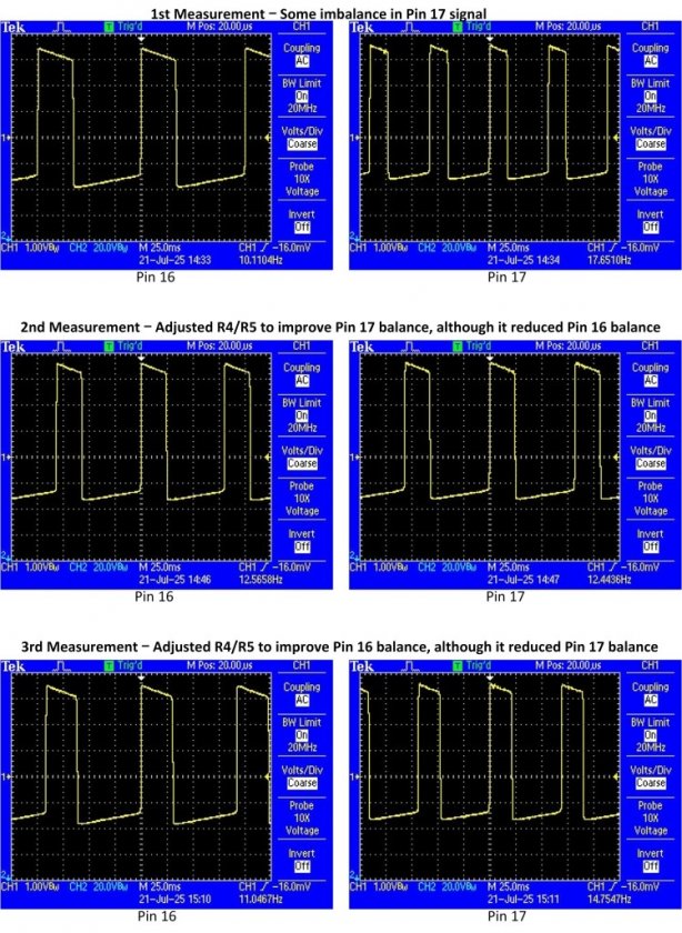 Figure 12: Measuring signal balance at microprocessor pins #16 and #17.
 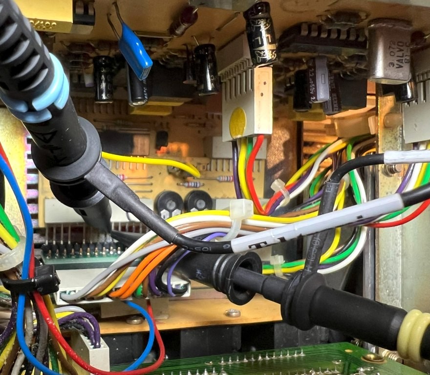 Figure 13: Oscilloscope probes attached to pin #6 QP-TR and pin #7 QP-TL.
 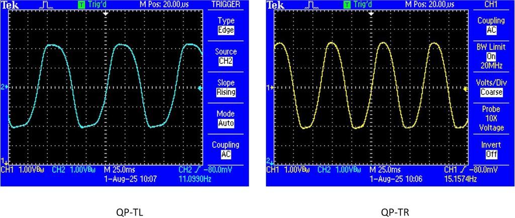 Figure 14: Measured light barrier analog signals QP-TL and QP-TR - acquired during tape Play.
* Looking at the zero-crossings of the light barrier analog signals in Figure 14, it can be seen the width of the positive sides are of similar width as the negative sides.
Hints* As mentioned previously, before performing this test check that the original 1k ohm R4 and R5 trimmer potentiometers have been replaced with modern closed-face types (Fig. 13). With the old open-faced trimmer, dust entry and corrosion will give erratic results. Before removing the old trimmers one at a time, mark their wiper positions with a felt pen (in case of mistake with installation of the new trimmers). When removed, measure and write down their resistance settings, then set the new trimmers to this value.
* If the trimmer's wiper positions are unknown or way out of range, setting the R4 and R5 trimmers to mid-position (500 ohms) is a good starting point and should work.
Assembly completed* Figure 15 shows the final assembly with Wi-Fi antenna mounted at the back.
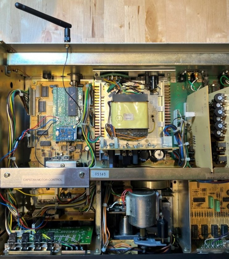 Figure 15: View of final assembly before attaching top cover. First operation test
1. With power switch set to OFF, inserting the mains cable into a mains outlet the display flashes "b710" and then displays the single red period (can be changed in configuration menu).
2. Flipping the power switch to ON, the display first flashes the default tape size "C 90" (can be changed in configuration menu), then displays "0000".
Connecting the device to Wi-Fi* Wi-Fi setup followed the instructions provided. The screen captures in Figures 16 and 17 were acquired with an iPad, although other devices (mobile phone, PC etc.) can also be used.
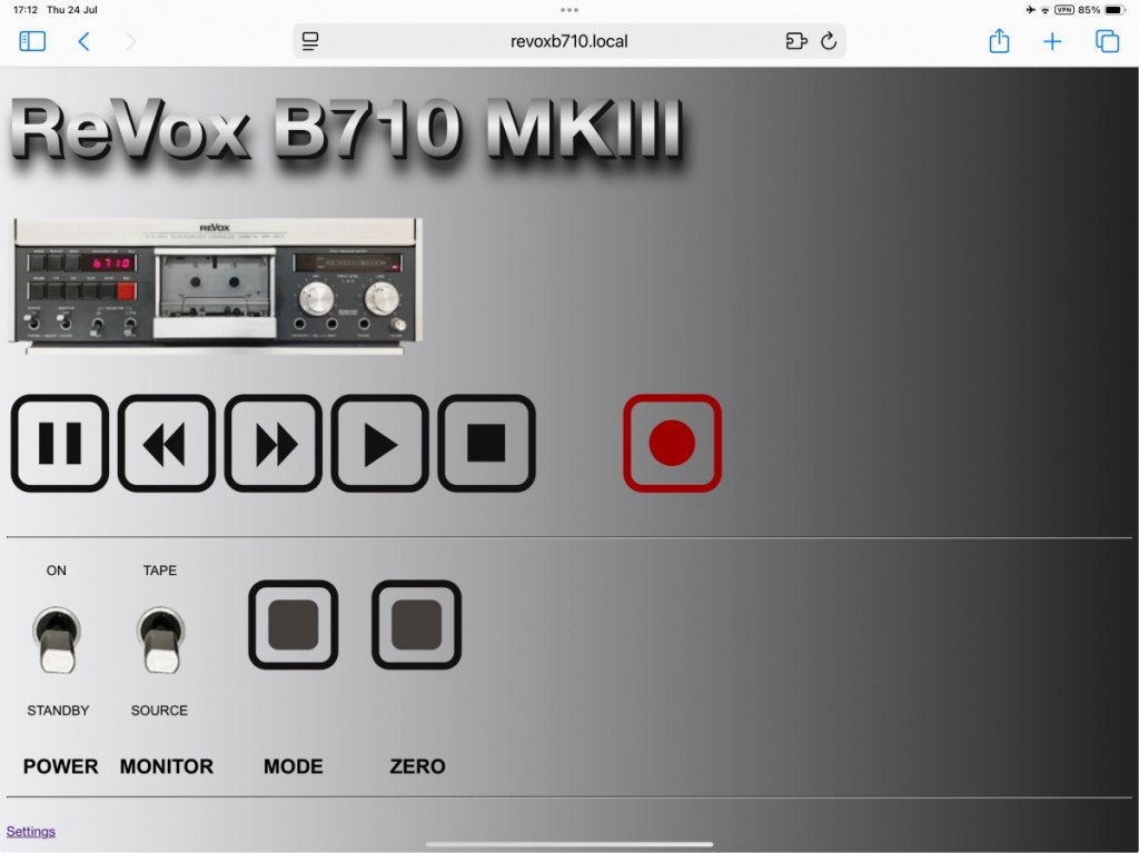 Figure 16: ReVox B710 local connection established.WLAN, IP and NTP Configuration
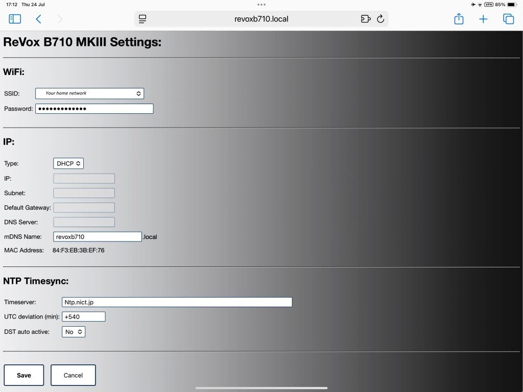 Figure 17: Home network settings completed - set to Japan standard time UTC +9 hours. Controlling the Back Tension by MK3 software
* As mentioned, an iPad was used for the Wi-Fi setup. Unfortunately, Apple does not support monitoring other device's IP addresses from an iPad, requiring a 3rd party app to be installed.
* I purchased the app 'Net Analyzer Pro' for this investigation, this app can also be purchased separately for Android. Although I haven't tried it, other 3rd party network analyzer apps would also work.
* Provided the B710 device is connected to mains power, the IP address can be pinged in either standby or power on mode. Specific IP address for this B710 on my home network is shown in Figure 18.
* Side comment, if you have a family in your home, it's surprising the variety of devices that get connected throughout the course of the day!
* Knowing the B710's specific IP address allowed me to change the software controlled back tension, presented in Figure 19 and Table 2.
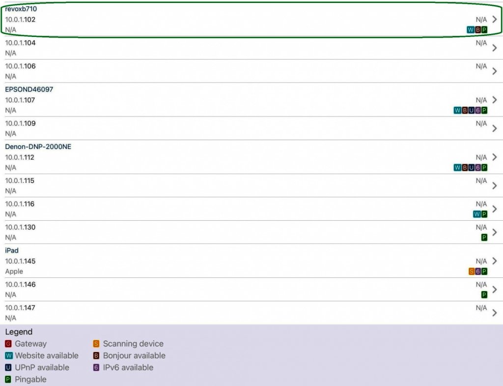 Figure 18: Partial listing of device's IP addresses connected on my home network - data acquired using Net Analyzer Pro.
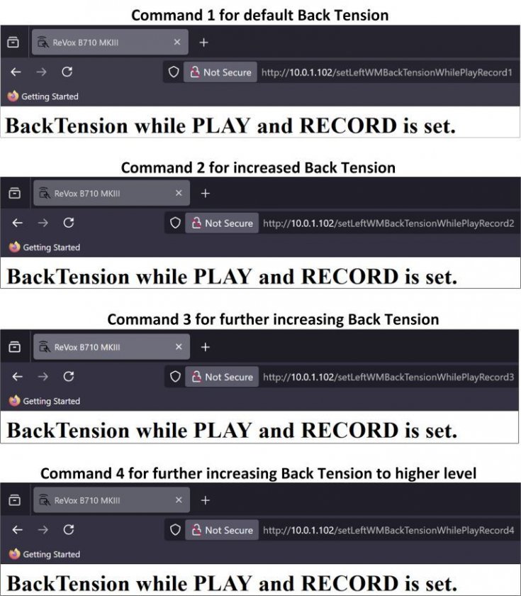 Figure 19: Confirmation of each Back Tension command sent by PC and received by B710.
 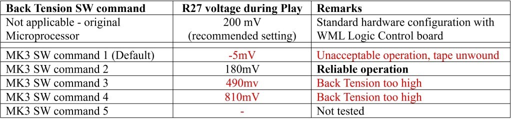 Table 2: Standard hardware vs. software controlled Back Tension - WML Logic Control board for Back Tension control remained in place.
* For all tests, the original small intermediate board (Wind Motor Left - Logic Control PCB) for Back Tension control remained in place. This small intermediate board can be seen in Figures 5 and 6.
* The MK3 software-controlled default Level 1 for Back Tension, in combination with the installed Wind Motor Left (WML) Logic Control board proved inadequate, causing tapes to slip sideways and unwind.
* On the other hand, the installed WML Logic Control board together with the MK3 software-controlled Back Tension Level 2 provided the most reliable operation - no unwinding or slipping of tapes. The voltage drop of 180mV measured across R27 (Fig. 20) was close to the standard hardware setting of 200mV. This setting was retained for all operations.
* Just to mention, the highest level of software controlled Back Tension, MK3 SW command 5, was not tested for risk of exceeding safe operation.
* Depending on the hardware configuration and installed modifications, results obtained with other B710 tape decks will be different from these results.
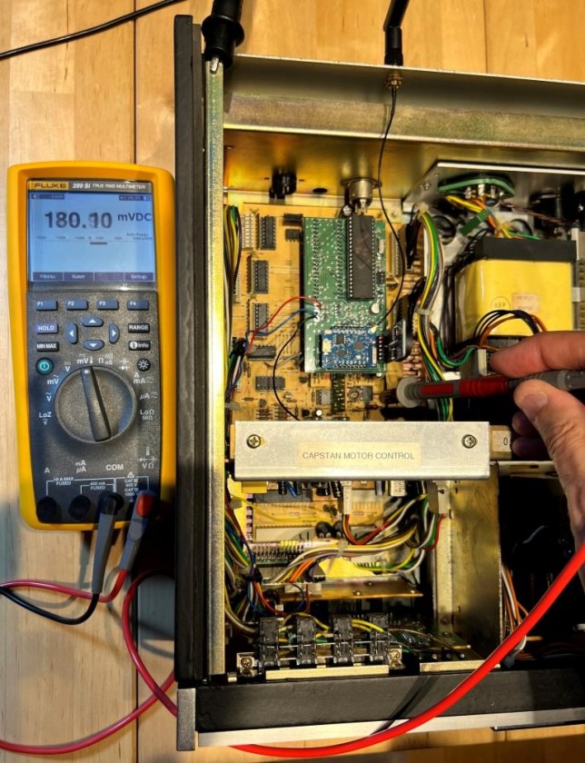 Figure 20: R27 voltage drop with MK3 software command 2 - measured during Play Performance check - Wow & Flutter measurement
* To verify there was no degradation in tape performance after installing the MK3 kit, two independent measurements of W&F were made using the Analogmagik LP test program. This comprehensive test program adheres to the Audio Engineering Society (AES) standard for calculating W&F.
* AES W&F results using test tapes supplied by GennLab and ANT-Audio are shown in Figures 21 and 22, respectively.
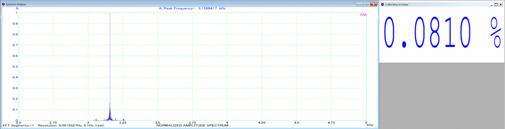 Figure 21: Example of AES W&F measurement acquired with GennLab test tape.
 Figure 22: Example of AES W&F measurement acquired with ANT-Audio test tape.
* In both cases the W&F measurements were well within the ReVox B710 specification of 0.1%, and in excellent agreement with the AES W&F results obtained in the two previous tests, confirming there was no degradation in performance.
A.
ReVox B710 Tape Deck - Successful Wow & Flutter Restoration. https://www.audiocircle.com/index.php?topic=190279.0 B.
ReVox B710 MK1 Tape Deck - A Wow & Flutter Software Comparison Test. https://www.audiocircle.com/index.php?topic=190768.0Final notes* Installing the MK3 kit was straightforward following the instructions provided. If desired, the kit is easily uninstalled, should the need arise to revert to original configuration.
* Apart from the clever feature of remote controlling the B710's functions from external devices (smartphone, tablet, PC etc.), the accurate counter and Network Time Protocol synchronized clock were other nice features.
* While the kit does not alter sound quality (nor does it claim to), cassette tape motion was noticeably improved with a smoother and quieter fast forward and rewind.
End of report.


