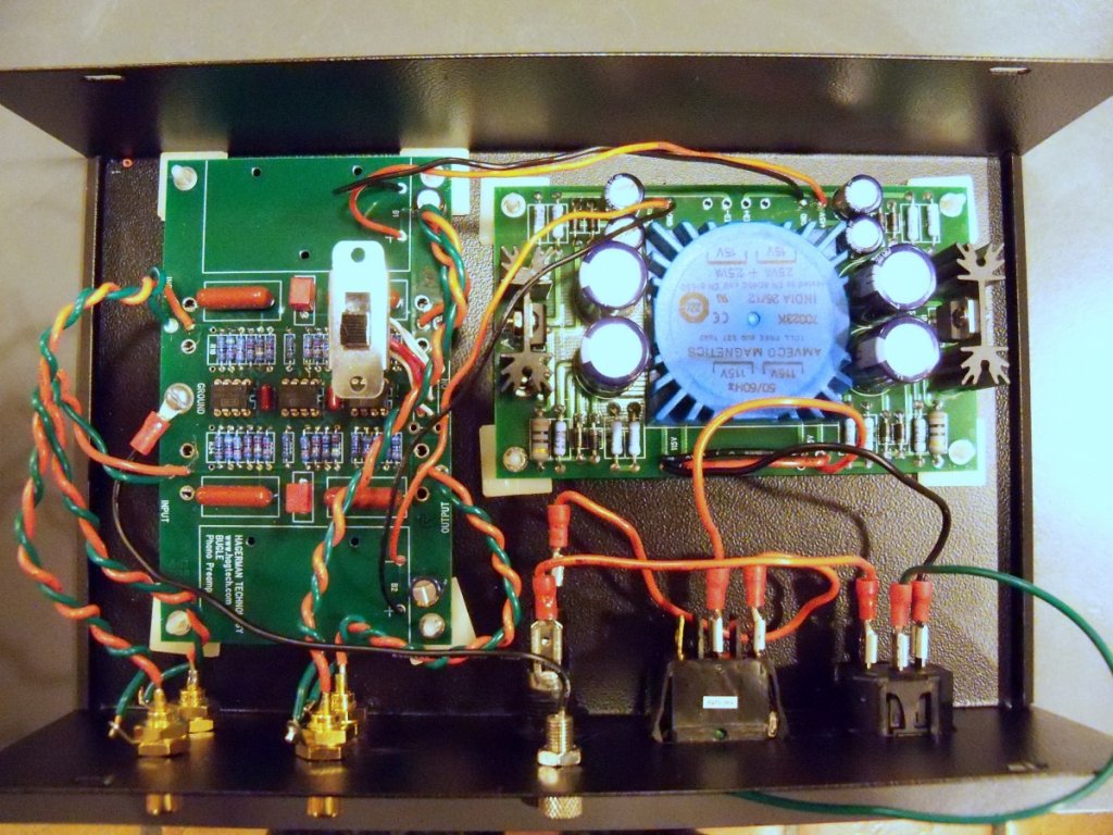
Poty -- Sorry to be so long in responding (I was on vacation last week), but thanks so much for your diagram; this is exactly what I needed! I had already started assembling things before I saw your post, so I have a couple of questions. I have attached a photo of my progress to date to give you an idea of what I've done. (Please ignore the IEC ground being connected to the outside of the case; this is a temporary thing until I put another grounding post in the chassis.)
1) I am using spade connectors at the power inlet. Can I simply crimp two wires into the connector at the negative terminal then run one to terminal 3 of the switch and the other to the power supply board?
2) When I read your power connections to the Power Supply Board from top to bottom, you have Hot/Neutral/Hot/Neutral. Mine is currently wired the exact opposite (i.e., Neutral/Hot/Neutral/Hot). Should I rewire or does it not matter? Since I used spade connectors, it's not a big deal to rewire; I can just swap the hot an neutral connections at the IEC. But then my anal-retentive gene will kick in and I'll be forever bothered by the fact that I have a black wire as hot and a red wire as neutral

3) I noticed you eliminated the PSB ground to Battery 2 negative connection. Does it matter if this is connected or not? (Mine currently is.)
4) You mention insulating the RCA shells from the case. The ones I installed have a thin plastic ring on the outside of the chassis. Is this what you mean? Or do I need to add another plastic ring where the jack touches the inside of the chassis?
I must say, this project has been a very satisfying introduction to electronics but I wouldn't have gotten this far without the amazing help of everyone on this forum. Thanks to you all!