So I modified the
Zo formula to account for the 220 ohm plate load resistors (R
p) in the Clarinet. Basically, I can't see any reason they shouldn't be added in series with the dynamic value r
p:
Zo=[(r
p2+R
p2)(R
k+r
p1+R
p1)]/[r
p1+R
p1+r
p2+R
p2+R
k(mu2+1)]
Using circuit values;
Zo=[(8900+220)(680+8900+220)]/[8900+220+8900+220+680(16.6+1)]=2959
Adding the series output resistance (R311);
Zo=2959+220=3179
Interestingly, subbing a 12BH7 (r
p=5660; mu=15.7) for the 12AU7 lowers the output impedance by about 40 percent;
Zo=[(5660+220)(680+5660+220)]/[5660+220+5660+220+680(15.7+1)]=1670
Zo=1670+220=1890
Anyway, I reread John Broskie's three blog entries dealing with his "SRPP+" and more and more sinks in with every reading. Posted below is the circuit design for his SRPP+ iteration. It differs from Jim's Clarinet design in that there are no plate load resistors and no grid stopper on the upper triode. A series output resistor is not specified.
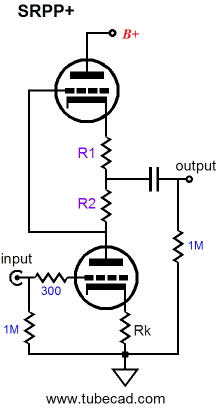
The "+" in SRPP+ is meant to indicate an SRPP circuit substituting a voltage divider (R1 & R2 above) for R
k2. The voltage divider maintains the desired amount of resistance for a certain bias point of an SRPP circuit, while also tapping the circuit's output from a point where the current contribution between the tubes is better equalized, lowering distortion.
In Broskie's own words:
For example, the following formula tells us what the optimal load impedance is for a given triode and Rak value:
Rload = (mu*Rak – rp) / 2
Thus, if we use a 6H30 with 250V B+ power supply and 300-ohm cathode and Rak resistors (mu = 15.4 and rp = 1380), the optimal load impedance will be 1620 ohms, which is great if that is the load we wish to drive. But what if we planned on driving 300-ohm headphones instead? Then we would use the following formula which gives the optimal Rak value for a specified triode and load impedance:
Rak = (2Rload + rp) / mu
I know I already brought up the following formulas, but I would like to run through it with numbers to show how Broskie's circuit changes work and why - as I have now realized - the "+" will not work with the Clarinet. The formula in the quote above provides the ideal R
k for a given load. In the provided example, the load is 300 ohm headphones:
R
k = (2R
load + r
p) / mu[/quote]
=[2(300)+1380]/15.4
R
k = 129 ohms
The problem is that 129 ohms is so low that the triode dissipation limit is exceeded. Using the formula below, Broskie shows how the R
k can be converted into an optimized voltage divider that maintains the 300 ohm resistance that keeps the dissipation to a safe level and helps drive low loads:
R2 = r
p2/2mu + R
load/mu + R
k2/2
R1 = R
k1 – R2
Solving for R2;
R2 = 1380/30.8 + 300/15.4 + 300/2
R2 = 44.8 + 19.5 + 150
R2 = 215 ohmsSolving for R1;
R1 = R
k1 - R2
R1 = 300 - 215 = 85 ohmsThe problem for us is that the load in this scenario is 300 ohms. Using the values found in the stock Clarinet circuit (R
k2=680; R
p=8900; mu=16.6) and assuming the sort of load an power amplifier might present (50K), we run into a problem:
R2 = r
p2/2mu + R
load/mu + R
k2/2
R2 = 8900/33.2 + 50000/16.6 + 680/2
R2 = 268 + 3012 + 340 = 3620 R1 = R
k - R2
R1 = 680 - 3620 = -2940A negative number means the Clarinet cannot be optimized with those values. Using Jim's modified values (R
k2=1200; R
k1=820) doesn't help either:
R2 = r
p2/2mu + R
load/mu + R
k2/2
R2 = 8900/33.2 + 50000/16.6 + 1200/2
R2 = 268 + 3012 + 600 = 3880 R1 = R
k1 - R2
R1 = 820 - 3880 = -3060Subbing a 12BH7 (r
p= 5670; mu=15.7) for a 12AU7 just makes it more incompatible;
R2 = 5670/31.4 + 50000/15.7 + 1200/2
R2 = 181 + 3185 + 600 = 3966 R1 = Rk1 - R2 = 820 - 3966= -3146How about decreasing the load to 10K?
R2 = 5670/31.4 + 10000/15.7 + 1200/2
R2 = 181 + 637 + 600 = 1418 R1 = Rk1 - R2 = 820 - 1418= -1876So basically, the problem we encounter when trying to employ the SRPP+ for linestage use is that the sort of loads your average linestage is going to run into are too large for this sort of modification. In fact, using the 12BH7 figures from above, you would need to be running the Clarinet into 1K ohm loads or less in order to optimize it.
So my main concern is that while I'm fine running the Clarinet into the 100K ohm load my tube amp would present, running the Clarinet into that same amp and an active subwoofer simultaneously (12K ohm input impedance; combined load of about 10K) would have some drawbacks. Exhausting any sort of tweak to fine-tune the Clarinet circuit for this sort of duty, I'm probably best off making only one change; increasing the output capacitor to 2.0uF:
Hz
-3dB=708/[(1+1834*C*(
Zo +
Zload)]
=708/[1+1834*.000002*(1890+10000)]
= 16
[an output capacitor of only 1.0uF with a 10K load yields a -3dB of only 32Hz, which is too high]
Thanks Poty!

