OK, so after all the above verbiage, surprise! Current plan is to replicate TomS' build below (similar to jtwrace in same chassis).
I'll draw chassis ID on graph paper, specifying exact locations and dimensions ASAP for member TrungT's gracious CAD work. I must order binding posts to measure chassis insulators for holes.
Meanwhile, as soon as we all agree I'll forward specs to Mike for cutting cost (hopefully free but no promises). BTW, last I looked HT CoZ had only one orphan mono chassis so it's this or dust off your drill press.
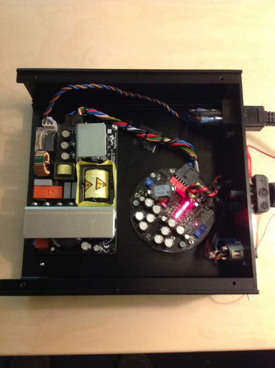
Again: larger chassis dimensions change nothing. PCB relationship is fixed by umbilical cord (shown) length and flexibility or lack thereof. It's quite stiff and even more so after twisting and tightly fixed with wire ties. Bruno is fond of the twist, as in wire, not the dance, though he may also like the dance, I don't know.
1. Seven small round base holes, diameter TBD (3 amp, 4 ps)
2. One IEC receptacle far right looking from rear
3. Two holes for aforementioned binding posts, centered horizontally, about 1/3rd from top vertically (leaves room for me to install a second set for bi-wire, which I presume no one else wants but please advise). What horizontal spacing between black/red? 3/4" for dual banana seems appropriate even though I much prefer tinned wire in the post hole over any banana.
4. One XLR female chassis jack far left looking from rear
11 holes total if Mike is reading this.
Specify when ordering/paying: aluminum face no extra charge or add $5 for black face (presuming Mike allows mixed order).