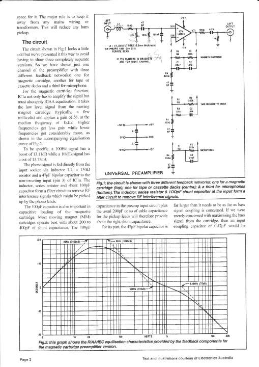
G'day Neo, I've built so many phono stages over the years I could almost do it in my sleep! Yes Jaycar here in Australia market the kit. The kit has been around for quite a few years and remains popular. The board is actually designed as a 'universal' preamp which can be configured to specific applications like RIAA EQ, tape and general purpose microphone preamplifier. Many of the more basic (and well priced) commercial phono stages pretty well use this 'standard' circuit.
Here are a list of my suggested tweaks for anyone interested:
I almost can't believe the improvement!
Every record now sounds 'better'...cleaner, more extended and just so 'nice and musical' to listen to. I'm wondering which tweak has had the biggest effect and given my past experience with loading changes with the Shure M97xE, I suspect my rearrangements of the 'front end' have probably had the biggest effect, although all the others have likely also 'contributed'. This little thing now sounds every bit as nice as my ESP P06, and the only apparent difference is output level and slightly more 'airy' treble from the P06, but they both sound rather nice!
I've been staring at the 16 KHz area of my audio spectrum analyser display in order to see any evidence improved treble response, and there is plenty and my ears confirm it too.
For those who might to build the standard kit here are, here are my suggested 'tweaks' (ok circuit changes).
Install a high quality 'machined' IC socket and install an OPA2134 dual op amp.
Install a wire link in place of .33 uf capacitor on the output of the op amp on both channels
Install a wire link in place of the 'L1' radio frequency choke on both channels.
Install wire link in place of the input 47 uf bipolar electrolytic capacitor on both channels
Do not install the 100 picofarad input loading capacitors unless your MM cartridge requires a high level of capacitance loading.
Simplify the input loading resistor to only one resistor of the required value (eg 47 k or 62 k for the Shure M97xE).
Install a wire link in place of the 150 ohm 'series' resistor on the input on both channels.
Install a 1 uf bypass capacitors across existing 47 uf bipolar capacitors in the 'inverting' op amp input on the solder side of the circuit board. Regards, Felix.
Kit Details:
http://www.jaycar.com.au/productView.asp?ID=KC5038&CATID=25&form=CAT&SUBCATID=557http://www.jaycar.com.au/productView.asp?ID=KC5159&CATID=25&form=CAT&SUBCATID=557 