If anyone has been eyeing these boards and similar ones on ebay, I have some useful info for you.
I first built a preamp using the Conrad Johnson PV12L replica board widely available on ebay. Very poor performance due to design issues with the published version of the schematic that is on the web.
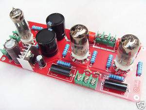
Recently I decided I wanted to try something without a cathode follower, so this 6N3 SRPP caught my eye.
The PCB, fully built with a set of tubes, arrived within a week of order from Hong Kong. PCD quality is quite nice, soldering is a bit skimpy. No documentation is provided at all.
I traced out the circuit and it is a classic SRPP. This led me to the first problems with the circuit.
1. The heaters are not elevated even though the top triode heater-cathode voltage exceeds the 100V spec for the tube.
2. There are no grid stoppers on the grid of the bottom triodes.
3. There is no load resistor at the output to drain the output cap if no load is connected.
I tried the circuit anyway fed off a 100K dual pot and got the following results:
1. Unbearable hum at all volume levels due to h-k voltage being exceeded.
2. No oscillation, luckily, but I’d be careful about trying WE396A tubes in here without adding grid stoppers.
3. Only 5V at the 6N3 heaters.
4. HT measured 240V using my 200-0-200 transformer.
I fixed the issues as follows:
1. Cut away the ground plane around each component in the heater supply and created an off-board bias circuit to get the heater supply to 1/3 of the HT. Very painful process, by the way…
2. Removed the blue LED’s at the base of the signal tubes as they created a path to ground for my newly isolated heater supply.
3. Added a heater transformer with 12V AC output rather than the 6.3V specified (basically once the 6.3V is rectified and smoothed there is not enough voltage under load to get the regulator to regulate).
4. Found I needed to add heat sink paste to the regulator to couple it to the heatsink as it now runs HOT.
Tested the unit. Hum is acceptably low but not gone and the unit now works properly. It sounds pretty darn good into a high impedance load 100K (tube amplifier) but a bit lacking in extension into a low impedance (10K) solid state amp.
What else is needed:
1. Increase heater supply smoothing cap value to reduce ripple.
2. Increase output cap value to allow better low end into lower impedance loads. Out of the box the unit is setup for 20K minimum loads.
3. Optimize the SRPP using John Broskie’s principles.
4. Add grid stoppers.
5. I have a feeling that this circuit will never be suitable for driving a 10K load, however, making it a bit less than suitable for my ClassDaudio amp as a buffer stage (with gain). I may rework it to use 12AU7 tubes and get the output impedance down a bit that way as the 6N3 is not ideal for this application due to its relatively high gain.
This was an interesting experiment, but a lot more effort than expected to get it working. This is NOT a plug ‘n play beginner project, even though it looks that way at first glance. If I was doing it again, I would buy chassis mount tube sockets and tag strips and build it with point to point wiring. Actually less hassle.
I hope someone finds this useful.


