Recommendations for where you can place bypass caps on your Clarinet and Cornet2

0 Members and 1 Guest are viewing this topic. Read 4670 times.

tubesforever

  • Full Member
  • Posts: 441
I have been getting a lot of emails and messages about where the Russian Teflon FT-3 0.10uf 600v caps should be placed on their boards.  This post is just my personal recommendations for cap placement where it achieved the greatest impact in my own system.  I hope that as others experiment they will post their results in this same thread.  This will be very helpful to others that want to experiment in the future.

Also, I want to thank all of you who have expressed appreciation for the group purchase.  It has consumed a lot of my time and effort for the last several weeks.  However I am cheap and I love a great deal.  I know there are a lot of us out there that just need an easy way to evaluate teflon bypass caps to see if they fit our requirements.  The group buy helps us evaluate these caps and a great overall savings.  I like that! 

A side benefit of the group purchase has been to get a chance to communicate with so many of you out there.  This is one reason why DIY captivates me, it is the great people and their experience and perspectives that help me enjoy this hobby to the fullest.  Jim Hagerman is a dream come true for a DIY afficianto.  I am so glad I have built my projects just to get a chance to learn more about the inner workings of circuit design.  I am better for DIY and for Jim Hagerman!

Before discussing the cap placement I should make a couple of overall comments.

First, these caps are simply parallelled  with the cap value that Jim Hagerman speficied for the pcb position with just two exceptions.  The incoming signal cap values for the Clarinet and Cornet 2 are identical to the 0.10uf values of the FT-3 caps.  This allows you to run the teflons alone in these positions which I will discuss below.

Second, you can quickly piggy back these caps for evaluation of their improvement to your equipment.  Use a vinyl tie strap to secure the FT-3 to the cap already soldered to the board. 

Here is a picture of my Clarinet. 

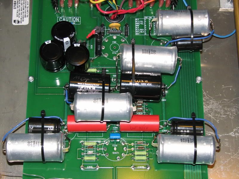
BTW I no longer bypass the first 47uf B+ capacitor.  It comes before the step down resistors.  Now I just bypass the C301 B+ supply caps going directly to the tubes.   This saves me one teflon cap from the picture you see here and sounds just the same.

Just solder a wire from the existing cap as close to the board as is easy to accomplish and then trim and solder that wire to the tie strapped FT-3 cap.  This way everything is nice and snug and you can easily remove the cap should you dislike what you hear. 

For permanent placement, you could consider soldering the 1.0uf value caps on one side of your pcb and the teflon cap on the other.  Anumber1 recommended this to me after seeing pictures of my piggybacked teflons!  I like a nice and neat case as much as the other guy.  I appreciate his recommendation.

This is VERY IMPORTANT....the outer casing of the Teflon cap is conductive aluminum.  You will get a nasty ground loop hum if this cap touches a ground which includes the case work.  If it bridges components it could cause a short.

I would recommend purchasing some 1 1/4 inch shrink wrap and cover the caps.  You could use electrical tape for short term protection.  I used clear shrink on mine with excellent results.  I purchased some 6 and 8 inch long vinyl tie straps from my local electronics and auto supply stores.  You will need these long nylon tie straps if you want to piggyback the caps for evaluation.  BTW you could leave this as a permanent mounting as well if you are not transporting your gear across country.

Now for the positions:

For the Cornet and Cornet 2 the first incoming signal cap is position C 203 right and left.  These are specified as a 0.10uf value 450V component as specified by the Auricap upgrade.  Simply remove what you have there and replace it with the FT-3 0.10uf 600v teflon capacitors.  These are mil spec aluminum and teflon film capacitors.  The Russian distributor has tested these and they function without failure to 1000 volts.   

The final signal cap position is C208.  These caps leave the most dramatic final sonic signature on the sound of your Cornet or Cornet 2.  The teflons have improved every one of the three 1.0uf caps I have evaluated.  I am confident you will benefit sound wise even if your unit has the orange drop caps. 

Paralleling the cap or piggybacking as I like to call it provides an additive value to that position.  You do not want to make a mistake of serially connecting these caps.  This would half their value.  In parallel your final uf will be 1.1uf +/- the % variance of the cap you selected. 

I am confident to say that for the great majority of Cornet and Cornet 2 owners by simply removing the existing C203 cap, replacing the C203 with teflons and piggybacking the C208 position caps you will achieve 90 percent of what I gained in my system. 

While you are in your case please verify the heater voltage going to your tubes and the other test point positions.  Make sure they are producing addequate voltage.  My C2 required lowering the H+ resistor to get the values higher for my heater voltage.  This improved my bass and the overall frequency response of my C2. 

For those wanting to get maximum dynamic response and bass slam, then you can consider adding teflons in parallel to the B+ supply bypass caps in positions C200 and C206. 

I found that the C203 cap position was critical in my system.  The teflons easily beat my Auricaps, Dynamicaps, K40Y9 PIO and Sprague Vitamin Q PIO caps I evaluated. 

On the Clarinet, you can use a solo pair of teflons for the right and left C302 position.  I ended up bypassing this with solid core silver wire instead of using a capacitor.  Jim Hagerman put this incoming signal cap in position to provide DC protection.  If your source equipment has DC offset built in, then bypassing this will be sonically rewarding.   If in doubt, the teflons would be the most sonically transparent cap you could use in this position. 

Next you will want to parallel the final signal cap in position C303.   I also use the teflons in parallel at position C301. 

I hope this helps clarify where the caps can go and where they might sound best.  Again, please add to this thread as you complete the process of adding the teflons in your equipment.  It will be great to have a historical perspective on teflon bypass caps. 

Cheers!

MusicMtnMonkey

  • Jr. Member
  • Posts: 47
Are those green resistors Kiwames?  (in between the teflon's at the bottom of the picture center)  The other resistors are some kind of naked Vishay??

Thanks for posting about the bypass caps!

tubesforever

  • Full Member
  • Posts: 441
The green resistors are Kiwami 2 watters I purchased from Percy Audio (no affiliation other than I really like Michael Percy nearly as much as Jim Hagerman!  They both keep me up to my elbows in fun projects!)

The Vishays are the S102 nudes that Percy sells for 11.75 each last time I looked.  Apparently you can buy the equivalents directly from the manufacturing souce Texas Components for a couple bucks less per resistor.

BTW the resistors make a world class sound level improvement to my Clarinet and Cornet2.  I will  probably try some Dale 2 watt resistors in place of the Kiwamis if I ever reconfigure these units.  I just do not feel the need to play with resistors any longer. 

The most important changes to me came with the S102 nudes.  Nearly equally as important is the sonic contribution of the big Russian FT-3 Teflon caps.  Both play a huge role but different rolls.  The resistors need to be clean and quiet so the signal is not muddled up.  These Vishay S102 resistors have the least mechanical and electrical distortion of any resistor on earth. 

The signal needs to pass with full authority.  The teflon caps accomplish this in a most impressive fashion.   I am in hogs heaven.  These things are relatively inexpensive to build yourself and they will beat up on some very expensive Stereophile class A recommended equipment.  In fact in many cases it was a fairly substantial step up in sonics.

Cheers!

MusicMtnMonkey

  • Jr. Member
  • Posts: 47
I look forward to trying the nude resistors  :icon_twisted:

FYI  the Texas Components 2575, Z201 type nude resistor was quoted to me at $9.40 each for quantity of 5, .1% tolerance.  With shipping it was about $11 a resistor.  Need to receive package and install parts before final verdict, but the purchasing process from Texas Components was easy, good phone help.

Sorry, back to FT-3's.  I'll be looking to experiment with mine in the future!

tubesforever

  • Full Member
  • Posts: 441
I am using the nudes only in the direct signal path where the signal is under 160v.  These are only 0.60 v in terms of rated value.  I can supply you with a list of the appropriate resistor points and values to  accomplish what I have done.  All the B+ resistors and the grid resistors need to be 1 watt or higher.

I think doing the resistor upgrades and the teflon capacitors are necessary to get world class sound from the Cornet 2. 

I just love what I am hearing.

And Pat, if you are reading any of this the Jupiters are on their way with some juicy Fairchild Hexfreds.   I will change out the Shottke diodes first and take a listen.  Then I will swap the beeswax for the Silver Supremes.  Later I will add back the teflons.

That should allow me to discuss what I hear regarding the Hexfreds, the Jupiters and the Jupiter with Teflons. 

analog97

  • Full Member
  • Posts: 373
Tubes,

Thank you for that helpful post identifying bypass positions on the C2 and Clarinet.  That looks very doable.  The hardest part seems to be the insulation required and fitting everything in.

jameshuls

I am using the nudes only in the direct signal path where the signal is under 160v.  These are only 0.60 v in terms of rated value.  I can supply you with a list of the appropriate resistor points and values to  accomplish what I have done.  All the B+ resistors and the grid resistors need to be 1 watt or higher.

Hi Jim, I would be interested in this info for my Cornet 2 build.

BTW, do you have any of the 0.1 uF teflons left - still waiting on my current order to arrive, and already I am wanting more! Thanks!

jameshuls

"I am using the nudes only in the direct signal path where the signal is under 160v.  These are only 0.60 v in terms of rated value.  I can supply you with a list of the appropriate resistor points and values to  accomplish what I have done. All the B+ resistors and the grid resistors need to be 1 watt or higher."

Hi Jim, I would be interested in this info for my Cornet 2 build.

BTW, do you have any of the 0.1 uF teflons left - still waiting on my current order to arrive, and already I am wanting more! Thanks!

tubesforever

  • Full Member
  • Posts: 441
Here are the Cornet 2 resistor positions where you might want to try the Vishay Nudes.  BTW either use them all, or use none. 

Interestingly, I blew one S102 Vishay on my Hagerman Clarinet while pulling a tube with the power on.  The resistor was between the B+ feed and the 12AU7 tube.  It took a few weeks for me to get in the replacement piece.

When I soldered in just that one resistor, the sound improved dramatically.  In the future I think I will replace this pair on the Clarinet with Dale RN 2 watt resistors.

Here are the Nude resistor recommendations and their positions on the board. 


2 each 47kohm resistors (for the Phono loading).  Position R200
10 each 221 ohm resistors Positions R201, 208, 212, 214, 219.
2 each 10kohm resistors Position R204

I am using the Fairchild stealth HEXFREDS instead of the Schottke diodes.  The HEXFREDS are only 1.95 each for the 4A 1200v pieces from Percy Audio.  I bought my Vishay Nudes there as well for 11.95 each.  I understand you can purchase the S102 equivalents from Texas Components for about 9.75 or so.

After replacing the Schottke’s with the Hexfreds I was able to remove the 5 watt R223 position resistor.  I have that bypassed with straight wire and I am showing 6.0 volts to my H+.  I think I have gained a little clarity getting rid of that R223 resistor.

At first I was not sure if the Hexfreds were worth the effort to put in with an existing build.  I would recommend them for any new build.  However after a couple of months of going back and forth in my mind, I have decided the Hexfreds are an improvement overall.  This is not a night and day issue.  However I am happy with the final results.  Make sure you heat shrink these before mounting them to the board.

jameshuls

That is very helpful info Jim! It is just so great for newcomers to the "sport" like myself to have access to people with experience - the learning curve is steep enough without having a go at it solo in the dark.