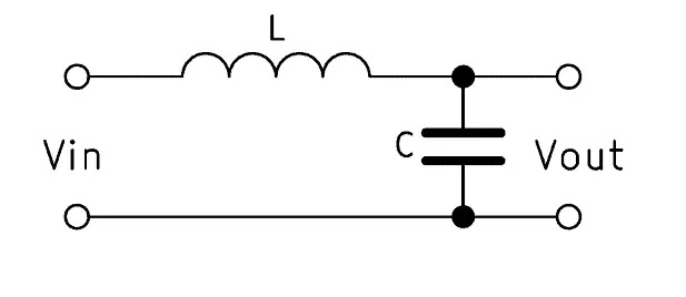
From the picture it is a 2-pole L-C low pass filter. The schematic would be:
The component values look to be marked on the inductor (L) and capacitor (C) that are on the board. The capacitance value would be the sum of the 3 devices that are in parallel.
The other two capacitors in parallel are probably a 1-pole high pass filter for the main speakers. They would go in series with the speaker + terminal to the amp.


