I have the components from Danny, and a schematic of where the parts go. But I'm slightly confused by what I'm seeing.
*warning* Extremely noobish questions follow, lol.
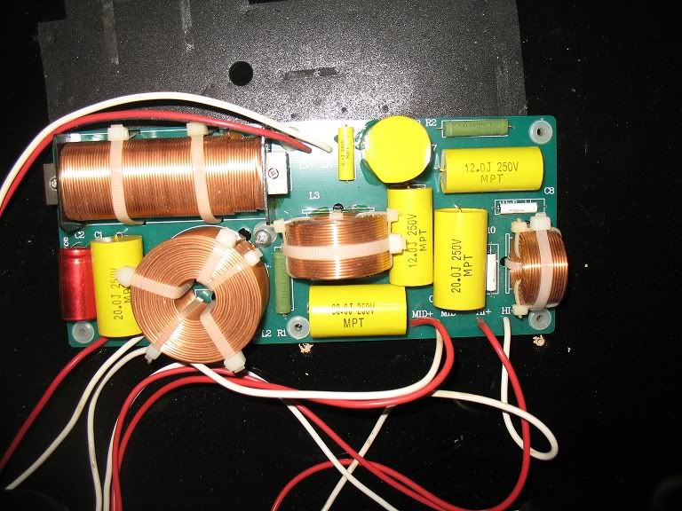
Ok, so here's my crossover.

Ok, for the tweeter circuit I'm supposed to replace a 12uF and 20uF polycap with Sonicaps of the same rating. I'm assuming the vertical yellow 20uF cap on the right, and the horizontal 12uF cap above it are the ones I'm looking for. Also in the tweeter circuit there's a 8ohm resister to be replaced, I'm assuming that's the one labeled R2 at the top right.
Then in the mid section I'm supposed to replace a 30uF and 12uF polycap with .1uF Sonicaps. Well, if I'm correct about the tweeter circuit then these are obvious. The 30 is down at the bottom and the 12 is tucked between it and the 20.
I'm pretty sure I'm correct in those assumptions, just wanted to double check.
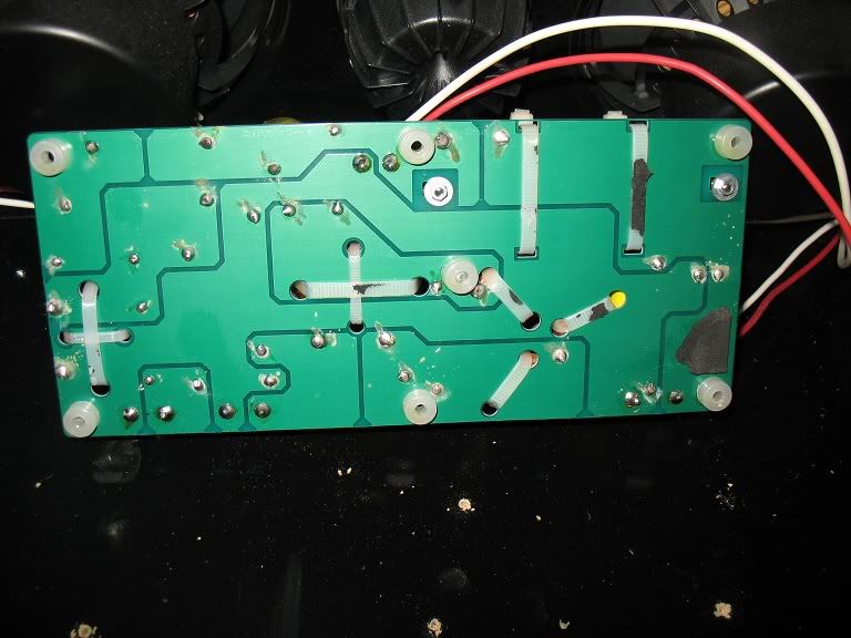
And another stupid question. I've worked with pcb's before and I can solder competently. But all the ones I've used have visible metal traces connecting the solder points. This is the bottom of the crossover.

There aren't any traces. Except for the dark lines, which don't actually touch most of the solder points. So, yeah. I mean it works so this doesn't really concern me, I'm capable of pulling components and soldering the replacements in. It's just not what I expected to see. Are the traces sandwiched in the middle of the board or something?