Comments on GK-1R CAD layout?

0 Members and 1 Guest are viewing this topic. Read 1980 times.

dayneger

Comments on GK-1R CAD layout?
« on: 30 Jan 2004, 05:16 pm »
Hey guys,

I'm hoping to finalize the layout for my GK-1R soon and was wondering what you think of this version.

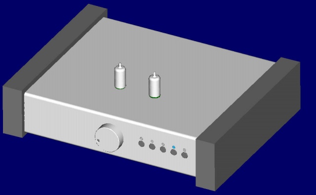
Here's the view from the top:


And this is looking at the underside of the chassis, which is shown in wireframe for clarity:


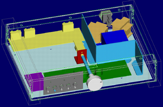
I didn't want to see screws on the top, so I'm mounting most of the parts on the separate light blue plate, which will then be glued to the chassis top.  I tried to route all power stuff around the side, behind the shield, and approach the preamp board from the front side.  The signal paths are pretty short and don't cross the power lines.

I'm going to slightly rewire the buttons so that they all end up on a row (I can use HT-bypass with the remote if I need, and I'll never have phono in there).  The IR-sensor is currently the position dot on the volume knob.  Still not sure whether it's worth the bother, it's just that elegance thing. . . :roll:

Any suggestions and comments are welcome!

Thanks,

:-) Dayne

Malcolm Fear

Comments on GK-1R CAD layout?
« Reply #1 on: 30 Jan 2004, 07:16 pm »
Hi Dayne
I am a big fan of half inflated innertubes and equipment support. Your layout does not lend itself to that.
The transformers look to be crammed together.

Carlman

Comments on GK-1R CAD layout?
« Reply #2 on: 30 Jan 2004, 07:41 pm »
You will have a very, very nice looking preamp when you're done.  I'm a novice DIY guy but, I agree about the transformers looking a little tight on space but, you may have thought about that more than me.  If I were building the GK-1 I'd put the transfomers in their own box.  

As to the IR eye, I think that's really clever.  However, from an audio purist perspective, would those wires running along the shaft add any potential problems with the volume pot?  EMI or otherwise?  If it doesn't add any problems (immediate or potential) sonically, I'd say go for it and have a really cool thing that sets yours apart from the rest.

I like the input selector as well.  The outside looks somewhat Proceed-ish... but with tubes.  I've always liked their look so, to me that's a compliment to its design.

It's clear you're obsessing/planning well ;)  which means you'll have a great preamp no matter what you end up doing.

AKSA

Comments on GK-1R CAD layout?
« Reply #3 on: 30 Jan 2004, 11:04 pm »
Dayne,

It's a terrific layout, very close to the one I'm using, and I can't see you'll have any problems with it at all.

Nice software!  What are you using?

You might consider suspending the analog pcb upside down with the tubes poking through at the top.   Support it from the base on vibration absorbing pedestals - eight of them.  I use long plastic inserts for mounting screws into walls.   You can then simply install the top cover over the top and tubes with all wiring attached to the base - no overlength wiring.  This makes it easier to make and reduces likelihood of hum.

Cheers,

Hugh

fred

Comments on GK-1R CAD layout?
« Reply #4 on: 31 Jan 2004, 04:01 am »
Just for the record, my transformers are very intimate with one another, only milimeters apart.  Does not appear to be a problem.

dayneger

Comments on GK-1R CAD layout?
« Reply #5 on: 31 Jan 2004, 02:14 pm »
Hey guys,

Thanks for the positive feedbacks!

Everything's modelled in Pro/Engineer 2001, a high-end 3D CAD system we use at work.  Comes in handy having access to that for important things, like DIY audio projects. 8)

I decided to cram the tranformers together so I could keep the signal paths undisturbed as much as possible.  Maybe I'm going a little overboard here!  I'll probably wire them up outside the chassis and then screw them into place when the tight work is already completed.

Malcolm, you're right about the innertubes.  On the other hand, it's not just an issue of left-right but also front-back.  If someone wants to use your isolation system they can just add mass inside the case in the appropriate areas.

I'm definitely no expert about EMI etc, but I doubt the IR sensor wires would cause any problems.  Anyone think otherwise?

Thanks again for the feedback!

:-) Dayne

cmscott6

Comments on GK-1R CAD layout?
« Reply #6 on: 31 Jan 2004, 03:34 pm »
Hey,

That's exactly the layout I used on my GK-1: transformers that close, on the diagonal, with the vertical metal shielding.  I don't have the "R" version, but in terms of power supply/transformer noise, mine is dead quiet.  Good Luck!