First bitten by the OB bug nearly four years ago, my self-imposed goal has been to build a new system each year taking into consideration what I have learned through reading, exchanging ideas with others and hours of hands-on experimentation and measuring. For the first three years that meant an increase in complexity, from a full range set-up to two ways, active three ways, biamping, mini-DSP, etc. All of these progressions had a few things in common. (1) increased size and weight; (2) questionable cost-benefit analysis; and (3) over time the complexity yielded to inconsistency and eventually frustration.
Inspired by the common-sense approach of folks like Martin King, this year I decided to revisit what I found so appealing about OB design in the first place. The primary goal was simple as was the design; namely, to build a classic, room friendly system that could be driven by a single amp to reasonable levels. The secondary goal was to test and implement an alternative way to compensate for dipole roll-off, through the use of a variable rheostat that enables the listener to dial-in the degree of “mid-scoop” needed to match drivers. Finally, the design must perform equally well in a 2-channel critical listening system and pull double-duty as the cornerstone of a multi-speaker home theatre system.
Configuration was for me, the first logical decision. I had decided early on that a single full range driver would not likely provide adequate levels when asked to perform HT duties. I have also decided through earlier design that in my setting, I prefer the sound of dipole radiation only up to a certain point. To me, the perceived benefit of more naturally occurring sibilant cues through diffuse reverberation gives way to a degradation of the intended stereo localization (image) as most recordings are mixed. This presented a bit of a design dilemma since most full range drivers are cones that freely emit a rear wave. I could attempt to absorb or deflect the rear wave, but that would only increase complexity and size. An alternative was a high quality chambered dome that could play low enough to mate with a variety of low frequency candidates. One such driver is the Usher 9950-20 which I have used in many designs elsewhere. With an Fs of 560 Hz, it can be crossed at 1800 Hz pretty effortlessly and even lower with a fairly steep slope. It is also to me, very natural sounding and uncolored and has an average efficiency of around 88dB.
The selection of a good low frequency driver was a daunting task. Again I had decided through earlier experimentation that I much prefer the sound of flat panel suspension to either H-frames or U-frames (open or damped) when the driver is asked to perform above 200 Hz. Perhaps in a 3-way design this would be fine, but in keeping with the primary objective, this was not an option. Since no external signal processing was to be used, and only a single amplifier, the driver would need to be highly efficient so the mids could be attenuated resulting in curve that favored the low-end. This would be done in an effort to compensate for the additional dipole roll-off. I have also discovered over the years that drivers with low weight and corresponding low moving mass do well in dipole arrangements, particularly where baffle vibration is concerned. The issues concerning a driver’s total Q in a dipole alignment have been thoroughly vetted on many websites. I completely agree that a high-Q driver yields a warmer low end, but I am not sure that should be the deciding factor, particularly where other methods of LF compensation are sought. A well controlled motor structure (low Qts) may also contribute to a greater linearity and corresponding lower distortion, particularly at high excursion. Finally driver diameter had to be considered. Having selected the Usher 9950 as the corresponding HF driver, I knew I needed a LF driver that was comfortable playing up to around 1800 Hz. B&C Speakers of Italy has been making high quality drivers since the mid 1940’s and have recently gained acclaim as the driver of choice in the Geddes line of speakers. They are extremely well made, have fairly smooth response curves, low moving mass, low weight, are highly efficient and have high excursion capabilities. After much analysis, I settled on the 10NW64 10” neodymium woofer as a good compromise for OB. With a SPL rating of 96dB 1w/1m and a conservatively rated excursion of 8mm, they would mate well to the HF driver selected for this project.
The crossover topology is fairly typical for this project. The woofer is crossed at 2000 Hz, 2nd order electrical LR-2. The tweeter is crossed at 1800 Hz, 2nd order electrical. There is an l-pad on the tweeter which yields a 2dB reduction in SPL and the polarity is not revered with that of the woofer.
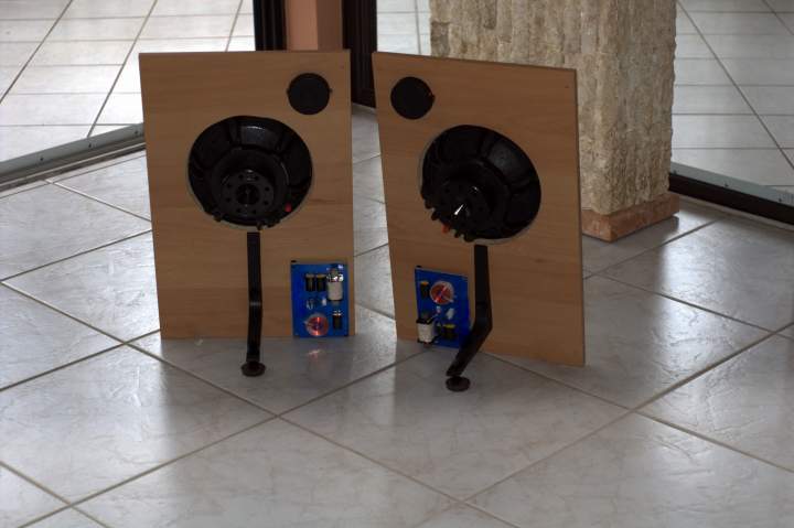
The apparent overlap of the woofers x/o is an intended part of the design. Unique to this circuit is a variable rheostat which is shunted at the woofer’s terminals and adds variable resistance to the crossover circuit as well as the load the amplifier sees. This affects the LF crossover point and effectively scoops-out the midrange, in a manner that can be dialed-in by the listener. In this design, it is an effective way to compensate for dipole roll-off, as there is an additional 8dB of SPL produced by the LF driver. Keeping resistance at the 2 primary legs of the potentiometer between 8 and 30 ohms, will result in a total load of 4-6 ohms per side, which should be safe for many SS amps. Dialing in additional resistance settings will fine tune the LF crossover point between ~1000Hz @ 4 ohms and ~1800Hz at 30 ohms with an infinite range of points in between. In my environment, a final resistance setting of 18 ohms produced the flattest on-axis in-room measurements and yielded a total load of 5.6 ohms per side that the amplifier sees. The additional 2dB reduction of the tweeter as noted in the previous paragraph (level match) was determined only after a suitable crossover point was selected and measured. One can simply alternate between dialing-in a crossover point, then tweeter attenuation, in that order for an infinite array of points within the intended range of this design. I suppose the rheostats can ultimately be replaced by two fixed l-pad combinations (series and parallel resistors) once a proper slope is determined resulting in a fixed version of this design, but I enjoy the flexibility as well as the ability to demonstrate my design concept on-the-fly.
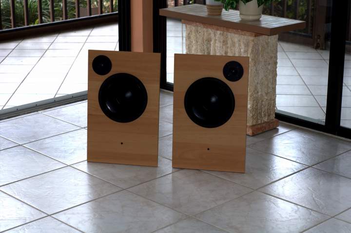
Final baffle size is only 15” wide by 24” tall. The woofer cut out is chamfered in the rear and centered 14” from the bottom. The tweeters are mirror imaged; their centers are 3” from the top and 3” from each side respectively. The baffle sits on 3 sorbothane pads in a tripod configuration, the rear pad is situated on an adjustable leg which can adjust +/- 1.5”, allowing baffle tilt toward the listener.
Powered by a single NAD 30 watt integrated amplifier, these things are smooth. They also play loud at low volume settings and do not strain when you crank 'em. The B&C suspensions are very stiff and take about 200 hours to fully break-in. As they break-in, the midrange smooths out and the bass gets more powerful, but has always remained defined, weighty and clear. Listening to Brian Bromberg on acoustic bass sounds amazing, as does the piano work of Keiko Matsui and vocal presentations from Cat Power and Diana Krall. All-in-all sometimes simpler IS better. I can easily transport them and get great (and consistent) results from a variety of amps and venues.


