ePot.V4 LDR Attenuator/Controller, Buffer & Power Supply

0 Members and 2 Guests are viewing this topic. Read 20933 times.

tortugaranger

  • Facilitator
  • Posts: 1756
  • Innovated passive & active preamp technology
    • Tortuga Audio
Re: ePot.V4 LDR Attenuator/Controller, Buffer & Power Supply
« Reply #20 on: 25 Oct 2023, 08:51 pm »
Interesting development Morten, I can't wait to see the V4 come to life, but I am curious about two implications of this new design change. Pico's onboard ADC is 12 bit, does this mean you are giving up on the idea of having 16bit ADC in V4? Also, is there a threat of potential RF interference from the Pico's onboard wireless and bluetooth chips?

Thanks!

The V4 will not be using the PICO's 12 bit ADC. The V4 has a separate dedicated 4 channel 16 bit ADC chip used only for calibration plus a 4 channel 12 bit DAC chip used for both LDR calibration and LDR control during normal operation. The V3 had the opposite - a 12 bit ADC and a 16 bit DAC. In hindsight, I believe accurate measurement is more important than more granular control provided the 12 bit DAC control is monotonic and repeatable which is it. I'm tweaking the LDR calibration algorithm somewhat as well to further optimize around the 12 bit DAC while taking full advantage of 16 bit ADC.

In the event using the PICO's WiFi or Bluetooth creates any problems, I simply won't use them. Initially they'll both be dormant until such time as I've come up with remote control solution that warrants their use.

tortugaranger

  • Facilitator
  • Posts: 1756
  • Innovated passive & active preamp technology
    • Tortuga Audio
Re: ePot.V4 LDR Attenuator/Controller, Buffer & Power Supply
« Reply #21 on: 9 Jan 2024, 09:02 pm »
Hi All,

I just published the first working draft of the V4 Hardware Manual which is now available online in our online documents section via this link: https://tortugaaudio.com/docs/epotv4-max-hardware-manual/

As the V4 remains under active development, there will likely be numerous changes to the manual over the next several weeks until the V4 is finally released. But those curious about the details of the V4, it's a fairly comprehensive description of the V4 Max hardware so far.

Cheers,
Morten


P.S.  We are currently having snowmageddon here in Bend, Oregon with probably a foot or more white stuff by tomorrow.

wgraft5

  • Jr. Member
  • Posts: 203
  • Wayne in Oregon
Re: ePot.V4 LDR Attenuator/Controller, Buffer & Power Supply
« Reply #22 on: 9 Jan 2024, 11:03 pm »
Hi All, P.S.  We are currently having snowmageddon here in Bend, Oregon with probably a foot or more white stuff by tomorrow.

Central Oregon will do that, then the sun will come out melt it and then Slushageddon! It freezes at night so then its Iceageddon and so on. lol Lived in the Bend area for 10 years or so. Back in the valley now. LOL

Wayne in Oregon

stvnharr

  • Full Member
  • Posts: 741
Re: ePot.V4 LDR Attenuator/Controller, Buffer & Power Supply
« Reply #23 on: 12 Jan 2024, 09:16 pm »
Looking forward to when the V4 comes out, when it comes out. I can do balanced without issues then.

tortugaranger

  • Facilitator
  • Posts: 1756
  • Innovated passive & active preamp technology
    • Tortuga Audio
Re: ePot.V4 LDR Attenuator/Controller, Buffer & Power Supply
« Reply #24 on: 19 Jan 2024, 11:27 pm »
Hi All,

I've now published a draft manual for the new optional plug-in V4 Solid State Buffer Module (SSBM.V4) that mounts directly to the new V4 Max board. Treat it as a working draft since changes are inevitable.

https://tortugaaudio.com/docs/epotv4-max-hardware-manual-copy/

The buffer module converts the V4 Max from a passive preamp/attenuator into an active version with optional gain (up to +12 dB) by simply pugging the buffer module into the same socket on the Max as the LDR Module. Then the LDR Module plugs into the buffer module such that you end up with a 3-layer board arrangement that looks roughly like the diagram below.

The buffer module design is an evolution of my earlier stand alone buffer board which has been in circulation for the past 3 years or so and has performed well.


tortugaranger

  • Facilitator
  • Posts: 1756
  • Innovated passive & active preamp technology
    • Tortuga Audio
Re: ePot.V4 LDR Attenuator/Controller, Buffer & Power Supply
« Reply #25 on: 28 Feb 2024, 06:11 pm »
A fair summary of the past 8 months...

July-Oct: Sort, cull & pack up everything while getting rid of 2 cars and a boat while recovering from a Cat 5 hurricane
Nov: Drive from Florida to Oregon and then stuff everything into a garage plus a storage shipping container next to the house
Dec: Holiday time with family
Jan: Unpack and set up Tortuga Audio operations
Feb: Get back to working on the ePotPi.V4 LDR Stepped Attenuator & Preamp Controller

And that's how you blow through 8 months moving from Florida to Oregon.

With all that behind me, I'm now focused again on completing development of the V4. The good news is over 90% of the firmware is directly portable from the V3 to the V4 hardware. The bad news is the I'm using a whole new development toolchain (collection of software applications) together with the new RP2040 based Raspberry Pi PICO microcontroller board which means an obligatory learning curve.

I can happily report that the initial firmware port is now basically done and is now ready for functional testing and refinement. I'm moving on to the 2nd gen V4 board prototype and with a little luck may only require 1 more iteration beyond that before it's ready for production. This means there's a chance of ordering production hardware as early as April with release/availability by May. And this could easily slip by 2-3 months because it can.

Meanwhile, back to work.

Cheers,
Morten


wgraft5

  • Jr. Member
  • Posts: 203
  • Wayne in Oregon
Re: ePot.V4 LDR Attenuator/Controller, Buffer & Power Supply
« Reply #26 on: 28 Feb 2024, 07:21 pm »
Thanks for the update. Glad to here you are settled in.
(Im)patiently waiting and saving my pennies for the V4 lol

Wayne in Oregon

tortugaranger

  • Facilitator
  • Posts: 1756
  • Innovated passive & active preamp technology
    • Tortuga Audio
Pre-Order an ePotPi.V4 LDR Attenuator/Controller
« Reply #27 on: 25 Mar 2024, 10:42 pm »
Hi All,

I'm opening up the V4 stepped attenuator & preamp controller for pre-ordering. Here's how the pre-ordering is going to work.

1) You can pre-order a V4 starting today, March 25.
2) You don't have to pay in full when you place the pre-order BUT you do have to pay a $50 refundable deposit.
3) There is no firm/estimated release date yet - May/June is achievable and I'm working towards that but no promises
4) Orders will be shipped in the order they came in - so FIFO (first in, first out).
5) When it's time to ship your order, you'll receive an invoice for the remaining amount due.
6) If you change your mind, your order will be canceled and the $50 deposit will be refunded in full.

The V4 product page is set up so that the default scope is: 1) a V4 board, 2) an LDR module, 3) an OLED display assembly, and; 4) an Apple compatible remote.  You can opt out of items 2, 3 and 4 if you already have these items but you will need them. The OLED display assembly includes infrared receiver and encoder plus cabling. A 5V power supply is NOT provided but minimally you can power the V4 from any Micro-USB cable.

Any existing quad LDR Module from your V3 board will work with the V4.
Most older OLED displays (Rev C or later) will also work with the V4.
An existing silver/metal Apple remote will work with the V4.

Here's the link to the V4 product page:  https://tortugaaudio.com/products/diy-preamp-components/epotpi-v4-max-electronic-stepped-attenuator/


Please PM or email (morten@tortugaaudio.com) me with any questions.

tortugaranger

  • Facilitator
  • Posts: 1756
  • Innovated passive & active preamp technology
    • Tortuga Audio
Re: Pre-Order an ePotPi.V4 LDR Attenuator/Controller
« Reply #28 on: 27 Mar 2024, 06:47 pm »
The V4 pre-order web page had a glitch which I believe has now been corrected. If you run into any problems, please let me know.

//Cheers |  Morten

Hi All,

I'm opening up the V4 stepped attenuator & preamp controller for pre-ordering. Here's how the pre-ordering is going to work.

1) You can pre-order a V4 starting today, March 25.
2) You don't have to pay in full when you place the pre-order BUT you do have to pay a $50 refundable deposit.
3) There is no firm/estimated release date yet - May/June is achievable and I'm working towards that but no promises
4) Orders will be shipped in the order they came in - so FIFO (first in, first out).
5) When it's time to ship your order, you'll receive an invoice for the remaining amount due.
6) If you change your mind, your order will be canceled and the $50 deposit will be refunded in full.

The V4 product page is set up so that the default scope is: 1) a V4 board, 2) an LDR module, 3) an OLED display assembly, and; 4) an Apple compatible remote.  You can opt out of items 2, 3 and 4 if you already have these items but you will need them. The OLED display assembly includes infrared receiver and encoder plus cabling. A 5V power supply is NOT provided but minimally you can power the V4 from any Micro-USB cable.

Any existing quad LDR Module from your V3 board will work with the V4.
Most older OLED displays (Rev C or later) will also work with the V4.
An existing silver/metal Apple remote will work with the V4.

Here's the link to the V4 product page:  https://tortugaaudio.com/products/diy-preamp-components/epotpi-v4-max-electronic-stepped-attenuator/


Please PM or email (morten@tortugaaudio.com) me with any questions.

familytree2000

  • Jr. Member
  • Posts: 12
Re: ePot.V4 LDR Attenuator/Controller, Buffer & Power Supply
« Reply #29 on: 30 Mar 2024, 10:28 pm »
Hi Morton.  When will the stackable active v4 buffer and power supply be available? 

tortugaranger

  • Facilitator
  • Posts: 1756
  • Innovated passive & active preamp technology
    • Tortuga Audio
Re: ePot.V4 LDR Attenuator/Controller, Buffer & Power Supply
« Reply #30 on: 31 Mar 2024, 09:21 pm »
Hi Morton.  When will the stackable active v4 buffer and power supply be available?

I expect both to be available soon after the V4 production boards are ready to ship. The plug-in buffer module and the PS are mostly done. Need to do final testing on both once the final V4 prototype has been proven out.

familytree2000

  • Jr. Member
  • Posts: 12
Re: ePot.V4 LDR Attenuator/Controller, Buffer & Power Supply
« Reply #31 on: 1 Apr 2024, 01:09 am »
 :thumb:

tortugaranger

  • Facilitator
  • Posts: 1756
  • Innovated passive & active preamp technology
    • Tortuga Audio
Re: ePot.V4 LDR Attenuator/Controller, Buffer & Power Supply
« Reply #32 on: 13 Apr 2024, 04:24 pm »
Pic of latest V4 prototype board without any parts installed. With some luck, this may be the next to last iteration. Have already made some minor mods to this layout. Will be building and testing out this board next week.


tortugaranger

  • Facilitator
  • Posts: 1756
  • Innovated passive & active preamp technology
    • Tortuga Audio
Re: ePot.V4 LDR Attenuator/Controller, Buffer & Power Supply
« Reply #33 on: 23 May 2024, 06:24 pm »
One thing I've learned the hard way (over and over again) is that the road to hardware/firmware development takes many turns and you never really know how long it will take until you actually arrive.

One of my objectives with the V4 has been to get away from having to use a very expensive and sometimes hard to find 4-channel 16 bit DAC chip. The 16 bit requirement is driven by the inherent behavior of LDRs when trying to regulate their resistance level in the high 10k's of ohms upwards of 100k. At these higher resistance levels, a very small change in control current translates into a big change in resistance (i.e. their gain becomes very large). This requires finer higher resolution control - hence the 16 bits.

Knowing this all too well, I still tried to get away with a low cost 12 bit DAC but was reminded all over again that the 16 bits used with the V3 build was indeed needed for a reason.

As a result I've opted to go with 16 bit pulse width modulation (PWM) instead of a 16 bit DAC. High resolution PWM doesn't require any special hardware and only requires 8 additional low cost passive resistors/capacitors for filtering. The PWM machinery runs as an independent peripheral within the microcontroller in parallel with with the firmware code.

Unfortunately, this requires yet another design/prototype iteration which means I have to wait until the first week of June to receive the updated boards that then have to be tested. So it goes.

tortugaranger

  • Facilitator
  • Posts: 1756
  • Innovated passive & active preamp technology
    • Tortuga Audio
Re: ePot.V4 LDR Attenuator/Controller, Buffer & Power Supply
« Reply #34 on: 25 Jun 2024, 06:10 pm »
Hi All,

Time for a V4 update.

Here we are with June almost over and the V4 is still not ready for production/release. What gives?

Roughly 4 weeks ago, I came to the realization that there was no way to accomplish a key goal of the V4 design if I insisted on staying with the Raspberry Pi PICO/RP2040 microcontroller.

First, let's review a key design goal. To accommodate balanced audio requires 2 boards because balanced audio uses twice as many audio signals as single-ended. Prior designs (the V25 and V3) handled balanced audio by designating 1 of the 2 boards to be the primary (right channel) and the 2nd board as the secondary (left channel) board. Each board was otherwise identical with its own microcontroller running identical firmware. The primary handled all the controls and had to communicate what to do to the secondary board. In turn, the secondary board had to communicate key info back to the primary board. Simple conceptually but a bear to implement cleanly and reliably.

I decided that with the V4, there would be only a single microcontroller running everything on both boards for balanced audio. This meant that the secondary board would be physically different than the primary and that the primary would have to handle more input/output which translates into needing more pins on the microcontroller chip. The RP2040 has 56 total pins but only 40 are made available via the PICO board and not all of those 40 pins are for control signals.

So simply put, I realized late in the development process that I could not achieve this goal given the low pin count available with the RP2040. I quickly pivoted and decided to revert to using an STM32 microcontroller instead of the PICO. Both the V25 and V3 had used STM32 microcontrollers so I was very familiar with their quirks and challenges. I first tried a 64 pin STM32G4 chip only to realize it was still 1 or 2 pins shy of what was needed.  So I bumped it up to an 80 pin model which handles everything with room to spare.

The good news is the code needed to run the STM32 is over 90% the same as the core code used in the V3 that had already been adapted for the V4 and the PICO/RP2040 chip. While switching from the PICO to the STM32 does not require reinventing the entire wheel, it does require a few additional weeks of concentrated work to adapt everything over.  I've already put almost a month's effort into adapting the STM32G4 chip into the design. Work is progressing but it will be August by the time the V4 is ready for production. In short, this change has put me roughly 2 months behind my original schedule.  :duh:

There are several advantages to this design evolution and a couple of drawbacks but the net benefits win out. It's a less complex design overall with fewer parts and arguably higher overall precision when it comes to LDR calibration and control. The V4 will now have 16 bit resolution on both the LDR current control circuit as well as the calibration measurement circuit. Prior designs used a mix of 12 and 16 bit resolution.

One unfortunate downside to this change is the elimination of built-in WiFi/Bluetooth communications. However, this feature can readily be added externally and linked with the V4 provided the necessary firmware is added to handle this - no small job but doable (future firmware upgrade would be needed).

So it goes.

Here's a screenshot of the updated V4 design with the STM32G4 microcontroller. Compared to the earlier design (shown below this pic), the updated design eliminates 3 complex external chips whose jobs are now all performed by the very capable STM32G4 microcontroller.


Below is a pic of the V4 with the earlier PICO/RP2040 microcontroller that proved too small for theapplication.


stvnharr

  • Full Member
  • Posts: 741
Re: ePot.V4 LDR Attenuator/Controller, Buffer & Power Supply
« Reply #35 on: 25 Jun 2024, 09:23 pm »
Thanks for this update. I eagerly await this new board so that I can go comfortably back to balanced operation.

Hikmer

  • Jr. Member
  • Posts: 61
Re: ePot.V4 LDR Attenuator/Controller, Buffer & Power Supply
« Reply #36 on: 1 Aug 2024, 12:57 pm »
Any updates for an August release?  Eager to get an upgrade to v4.

tortugaranger

  • Facilitator
  • Posts: 1756
  • Innovated passive & active preamp technology
    • Tortuga Audio
Re: ePot.V4 LDR Attenuator/Controller, Buffer & Power Supply
« Reply #37 on: 29 Aug 2024, 06:14 pm »


I’ve managed to chew up both July and August since my last update on the V4 so it’s due time for an update on the update.

Short version – the V4 is not ready yet.

Longer version. But it’s almost ready and I’m all but 100% certain that I will have production hardware in hand in October.

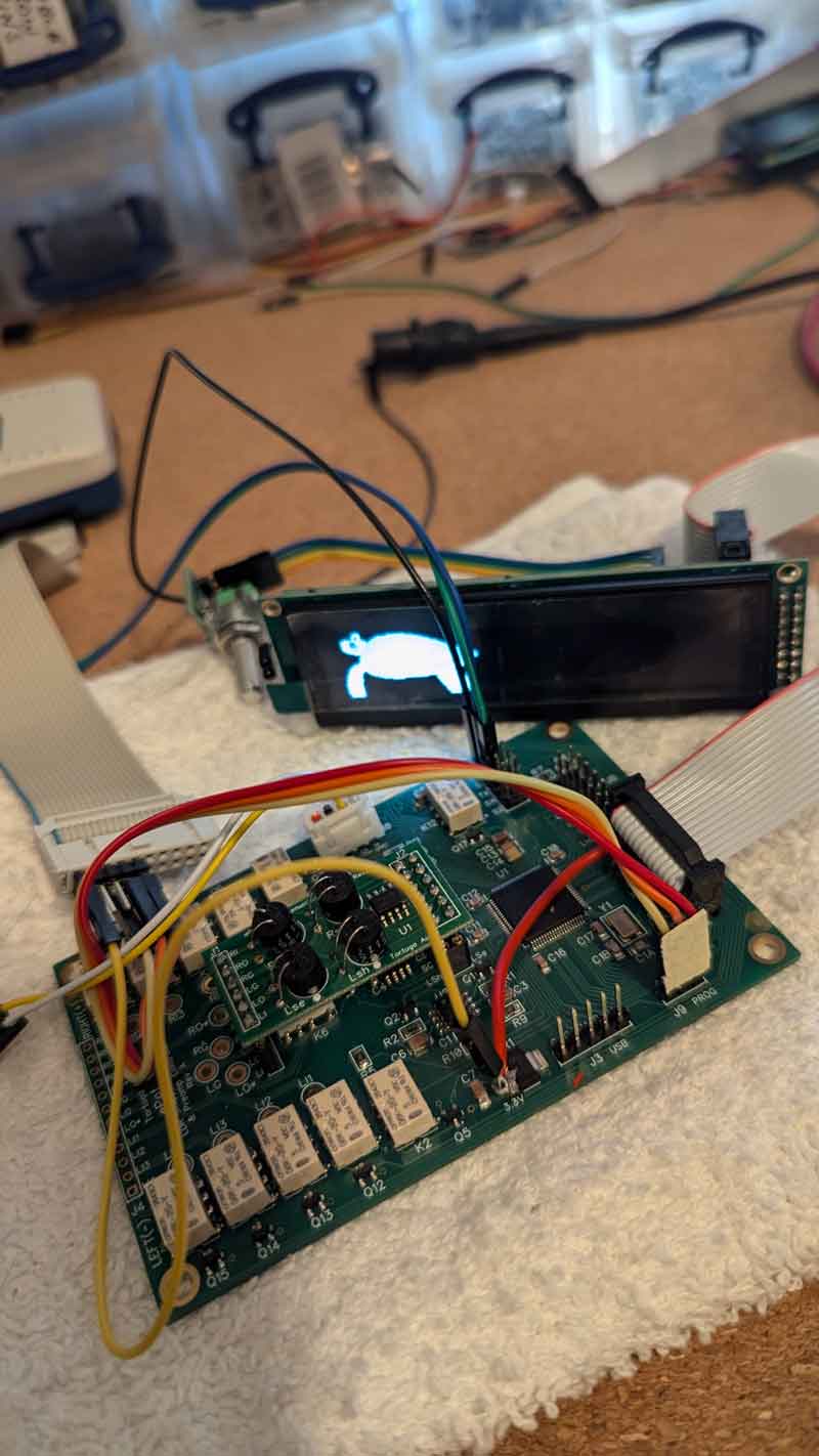
Elaborate version. As you may recall, I realized back in June that I would have to abandon using the Raspberry Pi Pico RP2040 microcontroller for the V4. Why? Because the Pico simply didn’t have enough pins for the job. Should I have known that going in? Perhaps. But development is a dynamic process and it teaches humility whether you like it or not.

Once I realized I had run out of micro real estate, I switched back to using an STM32 microcontroller albeit a newer and more powerful version that I had used in the V3. Fortunately, with the passage of time, the STM32 chips were finally widely available again after the Covid chip drought of 2020-2023.

With that decision made, I also made the decision to abandon the STM32 integrated development environment (IDE) software I’d used previously and adopt something that didn’t involve writing $1500 checks each year to a software company nor adopting a proprietary vendor toolset that would lock me into any particular vendor. Yes, that’s right, I was going rogue. And that meant an entire new IDE system for C/C++ embedded application development.

And that’s what I did for the entire month of July. I sorted through several free-to-low-cost IDE options, tried them out, cursed them out, flailed around a lot, cursed some more, and finally settled on one that sucked the least. If you have had any exposure to the world of embedded microcontroller IDEs, you know what I’m talking about. IDE’s mostly suck. Except when they don’t  and make it possible to code, compile, upload, and debug your software in real time on actual hardware. But until you get one to work properly it’s a special kind of hell getting up each day and breaking your pick on the same rock day after day only to realize you’ve burned up the whole month of July simply getting your tool to work. But I did get it to work…finally.

In August I finally made actual progress bringing up the revised V4 board with the new STM32 chip. Except for one particular bug which seemed to defy gravity until I realized I had shot myself in the foot by installing too small a EEPROM memory chip that kept overwriting its data because there wasn’t enough memory space for what I was using it for. Only took 2 weeks to sort that out. More of that humility being taught again.

So what’s left to do? I’d like to believe it’s mostly just clean-up and fine tuning but we shall see. Most of the code is mature and stable at this point but the LDR calibration coding has been substantially revised and updated and needs further testing. I also believe the V4 hardware/board is only 1 iteration away from final with only minor tweaks needed between the current prototype and the production version.

If all goes well, I’ll be placing an initial order for production boards later in September and have the first batch of production boards in hand by October. If all goes well.
Oh, and the new optional linear power supply and optional active buffer boards are both pretty much done as well. Those both use 100% conventional analog parts with no microcontrollers – easy peasy – kind of.

Cheers,
Morten