MC Bugle is done! (MC stands for Moving Coil and Mission Creep!)

0 Members and 1 Guest are viewing this topic. Read 7686 times.

cengclimbing

  • Jr. Member
  • Posts: 14


You probably are saying, "Wait a second...  The Bugle is a small SS design and I see tubes!"  Well this is a story of a Bugle that started modestly and through a series of upgrades, due to a little mission creep, has morphed into what is above.

A little history...

I needed a nice and cheap phono stage to use while my K&K audio pre was going through a few upgrades and an exterior rework.  I had built a Cornet 2 a long time ago and was confident that if Jim designed the circuit it was a good bet that the sound would be up to standard so, I ordered the PC boards for the Bugle and matching power supply and had plans to put the units in an old Hammond chassis I had laying around.  I built them stock and set for 60db of gain.  The sound was OK but compared to the K&K it was replacing it was a bit flat, hazy and one demential. To be fair, it is being compared to a phono preamp that costs 10x as much. 

But, the bones were there.  It got me thinking.

First upgrade...  I had a spare set of S&B step-up transformers sitting in the parts box.  To run them I would need to change a few resistors so I figured while I was desoldering anyway I would take the opportunity to change the rest of the resistors and the caps.  Mundorf for the caps, PRP and Kiwame for the resistors.  A couple of days hooked to Jim"s reverse RIAA...The sound opened up and the hazy presentation was gone!  In it's place was pinpoint imaging and a nice wide soundstage.  Vocals were a bit forward.  Still, there was a little upper midrange glare but it now was heads above the stock unit. 

I was thinking this was it.  Good enough.  But...

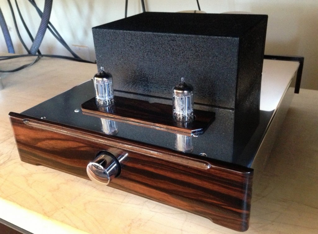
Second upgrade...  I had a blue LED going from the power supply while it was on the project board and figured out quickly that when the lights were low that blue light would drive me crazy.  I like the way tubes look at night.  Maybe I could kill two birds with one stone and get rid of the LED and address the upper mid glare by giving this thing a tubed output?  A few quick clicks and an Aikido cathode follower and power supply board were on their way. 

We are now getting away from nice and cheap and moving to really nice and not so cheap.  (Mission Creep has set in!)

The sound with the S&B TX103's into an upgraded Bugle into an Aikido cathode follower set up for 12au7's...  Excellent. Great mids, airy highs, wide soundstage and above all wonderful musical flow! 

Still sitting on a piece of plywood...

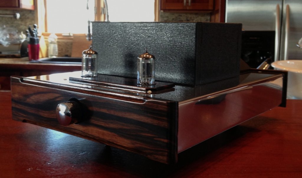
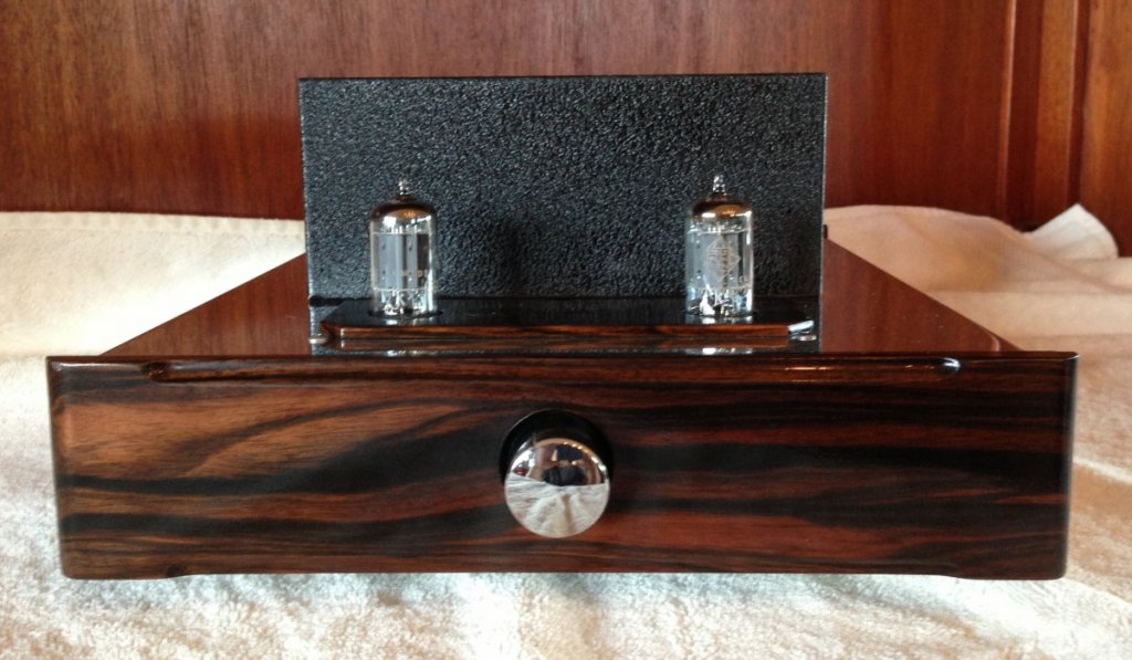
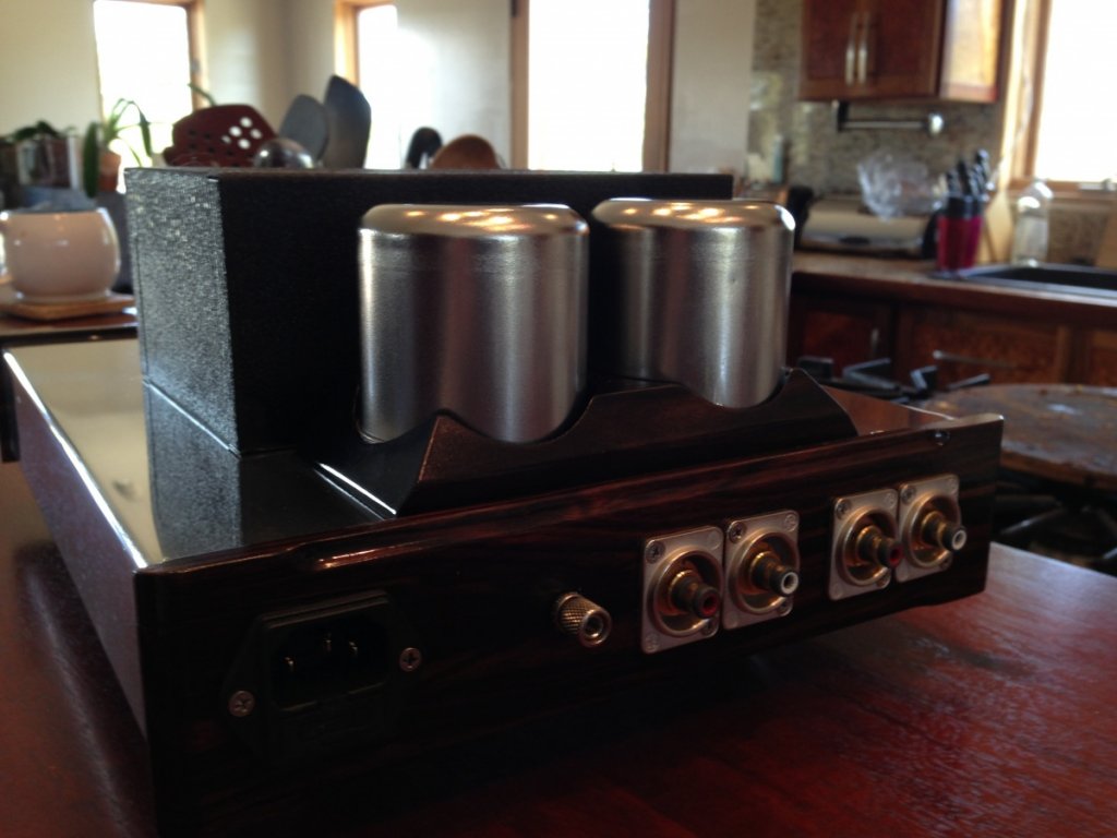
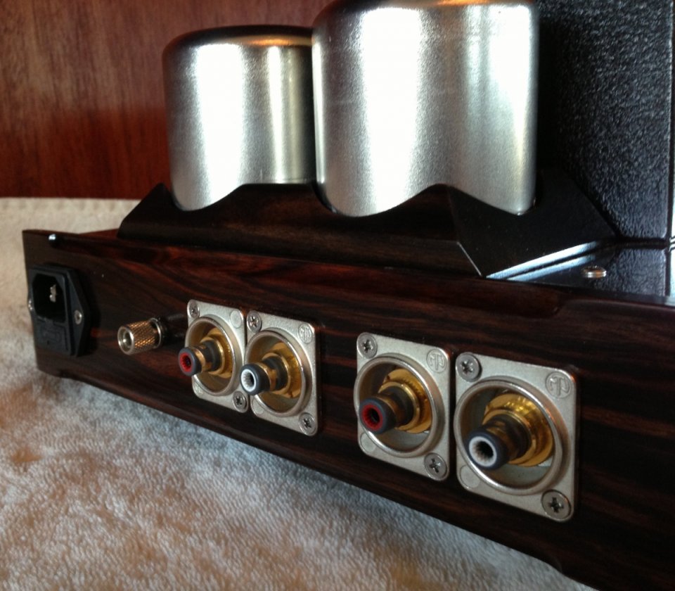
Third upgrade... This thing sounds so good I can't just stick it into an old used Hammond chassis now could I?  Again, a few quick emails and Mike at KM Audio Chassis had the aluminum bent.  I had some Ebony in the shop so he did the metal work and I the wood work.  The metal comes brushed but I took a little time and brought it to a full polish.  (We are now past mission creep and into the stage where my wife is asking me sarcastically when will this "quick" project be done?)

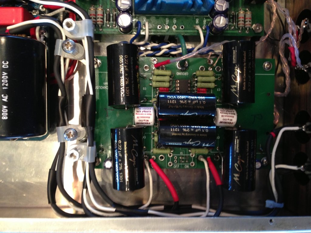
All together and it sounds good but...  What about some NOS Telefunkens or Mullards from the tube stash?  Yep.  They both sound excellent.  Mullards for the mids, Tele's for the top and bottom punch.  And while I'm at it maybe I'll stuff some Mundorf silver/oil caps in the output stage.  (I had the caps in the parts bin.)

It now looks and sounds as good as anything I have had in the system.  I've had it running a Dennon 103r, Shelter 501 mk2 and a Benz Ruby.  All sound wonderful and the Bugle shows off each cartridge's personality!

Here are a couple of pics of the build.
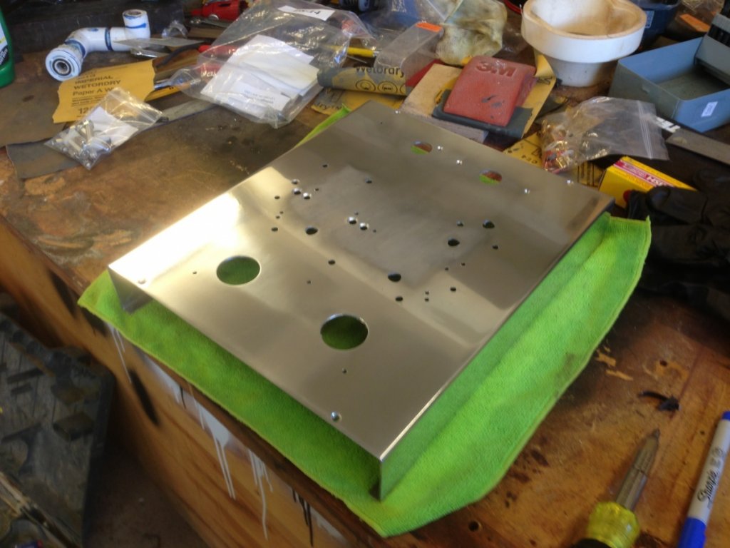
Lots of holes.


Shiny is good.


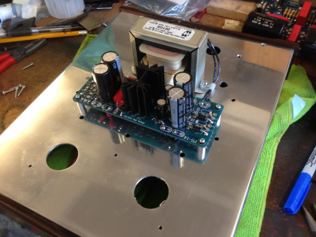
Tube Power Supply and Transformer.


The layout.  It all fits in a 10x12x2 chassis.


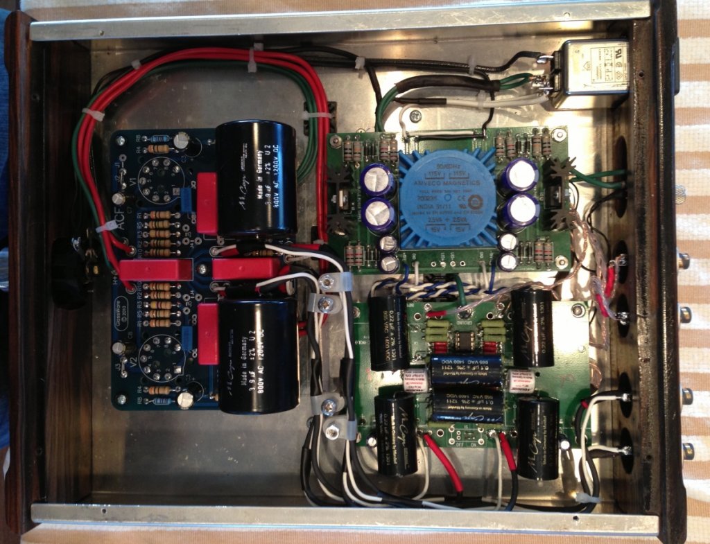
Jim's Bugle under the Mudorf caps.


Finished!


It's too bad that S&B no longer supports the DIY community.  The TX-103's are really special.


Thanks to Jim for designing such a great circuit.  One so good it lead to a month of extra work and a bunch of boutique parts.  It's now a keeper for the long haul!

Cheers,
C-


« Last Edit: 1 Jun 2013, 06:28 am by cengclimbing »

hagtech

Wow - that's some amazing woodwork!

jh

cengclimbing

  • Jr. Member
  • Posts: 14
Thanks Jim.  You, and the other designers, make stuff like this possible by offering your designs up to others in such a user friendly form.  I don't think I would have tried anything like this without printed PC boards and great support. 

Thanks.   

Jaxn

  • Jr. Member
  • Posts: 7
Simply brilliant!

Jack

cengclimbing

  • Jr. Member
  • Posts: 14
Thanks!  It's burning in and sounding great.  Just a few more tweaks to do when time permits. I'd like to try some different opamps in position 3 and change out the input caps on the tube cath follower to mundorf silver/oils. 

poseidonsvoice

  • Full Member
  • Posts: 4016
  • Science is not a democracy - Earl Geddes
    • 2 channel/7 channel setup
Wow! :notworthy: From one diy'er to another. Great attention to detail, parts execution, topology, etc...

Enjoy the fruits of your labor!

Best,
Anand.

galyons

  • Full Member
  • Posts: 477
Got my new kit from Jim.  You have set a pretty high standard!

Cheers,
Geary

mgalusha

Beautiful work, love it.  :thumb:

cengclimbing

  • Jr. Member
  • Posts: 14
Thanks guys for all the kind words.  This was a fun project all the way around.  As for your new Hag kit... Upgrade those resistors and cAps if the budget permits!  They make a ton of difference and Jim's circuit design really benifits from them. Also, if the aesthetics matter to you look up Mike at KM audio chassis.  With his help you can have a piece of gear that shines as well as sounds great for not much more than the cost of a simple Hammond box. 
 

galyons

  • Full Member
  • Posts: 477
...look up Mike at KM audio chassis. 

Google wasn't my friend on this one.  Do you have contact info?


Cheers,
Geary

cengclimbing

  • Jr. Member
  • Posts: 14
Absolutely!  Mike just took over building these after his longtime friend Keith Kirby pasted a few months ago.  The design is Keith's and I have to say, having Mike building these and making them available to the DIY community gives us all a great reasonably priced option.  There is nothing wrong with a stock Hammond chassis but these just bring our projects to another level.  Anyway...  Here is his email and I also included the ebay listing.  It's an example of what he can do and has available now.  (Farming is his "real" job.) He can build custom sizes and is doing one for a headphone amp project that I have cooking. 

Oh ya...  Just a quick note I feel I need to make...  I have no financial connection to Mike's company.  I'm just a satisfied customer. 

I've learned so much and discovered great suppliers though this forum and others, I hope that some DIYers benefit from the info.

kmaudiochassis@gmail.com
http://www.ebay.com/itm/281081716230?ssPageName=STRK:MEWAX:IT&_trksid=p3984.m1423.l2649

Cheers,
Chris
« Last Edit: 25 Jul 2013, 02:21 pm by cengclimbing »

galyons

  • Full Member
  • Posts: 477
Thanks.  I strongly believe a well engineered chassis is as important as the build components, especially with low level signals.  I built my Cornet2 chassis from scratch.  I wanted lots of real estate and protection from outside influences.  I got it, but the time and expense, (not having all the tooling and experience), was challenging.

I will take a look!

Cheers,
Geary

Folsom

It looks so nice! Mine is just in a grey box without any labels, on/off switch, and a big chunk-chunk feeling input selector knob (no labels :) )

I recommend better input resistors. I'd say something about the signal caps but you already replaced them, and the none signal caps!

I was using these, considered these, but have switched to these (haven't heard them yet though).

The signal is a little fragile to subject to the sonic signature of a Kiwame, at the input. I think the signature is appealing for phono preamp, but maybe not as heavily laden as on the input.

The stock choice of opamp is good, but sometimes these can be had cheaply on Ebay, and look to be maybe the best candidate short of discrete (expensive, and worried about RF a little bit on the first opamp in the chain).

cengclimbing

  • Jr. Member
  • Posts: 14
Thanks for the input. I guess some explanation on my parts selection would help others so here it goes.

To start: I have used the Vishay Nudes in my integrated amp when I changed the resistors but at $12-$17 a piece the cost started to rise a little to quickly.  I do agree with you that they are terrific.  At this price point though, I think the best bang for the buck was in the caps.  In fact I would have used the silver/oil supremes instead of the standard supremes had I thought that the circuit was up to it at the time.  I know now that it is but didn't have that experience when placing the first cap order.  I like the silver/oils and their smooth yet detailed presentation and think they would be great in this application.  I did have a few V-caps in the parts bin but not all that would have been required.  Just like the Vishays I thought the cost was a little high for the design.  As far as the Kiwame resistor choice on the input...  The part of the stock sonic signature that I was trying to quell was an unrelenting brightness.  This was evident with the Shelter and the Benz in an all tube system using 12au7's into el-34's.  My system, for good or bad, leans towards the romantic side of things .  Having never used a piece of gear based on opamps I figured, maybe incorrectly,  that the opamps and the inexpensive metal film resistors were largely to blame for this condition.  I had a reasonable assortment of Kiwames on hand and I enjoy the sonic signature they provide.  YMMV. Ask someone what their favorite resistor is and you will get a bunch of different opinions.  Add to that, asking what your favorite resistor is in what position and you will get another bunch of opinions.

If I were to do it again:  Mundorf silver/oil for the caps, and Riken resistors (NOS sourced from overseas) and I would solder the first two opamps in place. 

I would be super interested in your opamp recommendations.  It sounds like you have a  lot of experience with different types and it is the last part of the puzzle that I haven't worked out.  It seams like it is just as much, if not more, of a black art as tube signature so any guidance would be great.   

Lastly... As with all things audio, system synergy is the most important thing so I caution everyone to take my recommendations with a grain of salt.    What I have built works well in my system and while the K&K does most things better, I haven't enjoyed listening to albums any less with the upgraded bugle in the mix.  I could happily live with it for the long haul. 

Cheers,
Chris
« Last Edit: 25 Jul 2013, 02:25 pm by cengclimbing »

Russtafarian

  • Full Member
  • Posts: 1117
  • Typical reaction to the music I play
Is the tube circuit used as a buffer stage on the output of the Bugle or does it replace one of the Bugle's op amp gain stages?

Russ

cengclimbing

  • Jr. Member
  • Posts: 14
Currently I am running all three bugle opamp stages.  The tube stage is a follower after the last opamp.  Your question got me thinking if it is possible to bypass the last opamp and have it running straight to the cathode follower tubed stage.  Unfortunately, I have no idea if it would work.  Maybe Jim could chime in here?   I would be willing, if not anxious, to build another Bugle using the different parts specced earlier and having it go straight into the Aikido Cathode follower circuit.  If someone can look at the schematic and tell me where to pull the signal from on the PCB I would be happy to give it chance and report back.   

poty

  • Full Member
  • Posts: 616
You can get the signal from the top of R15. It's very likely you have an input capacitor and the grid leakage resistor in your tube buffer - you should remove both of them. I'd also look at the voltage ratings for C1 - the capacitor is unlikely to be presented by high voltage, but in the tube circuits it's better to be on safe side. I think 200V or more is enough.

cengclimbing

  • Jr. Member
  • Posts: 14
Thanks Poty!  I think I will give it a try.  This is the schematic of the cathode follower I am using.  I think I need to pull C1 but can you confirm and guide me as to what resistor needs to be removed?


I'm still in the infant stages of schematic reading. 

cengclimbing

  • Jr. Member
  • Posts: 14
Jim,
I was wondering if the opamps in positions 1 and 2 can be substituted with LME 49720HA's as suggested by Salis Audio? 

Thanks,
Chris

poty

  • Full Member
  • Posts: 616
Chris,
I did not see your cathode follower schematic and I should admit that you'll have to make more changes than I suggested.
First of all, the input tube grid is tied to B+ (through R5/R2 divider).  I'd use the C1&C5 in Bugle rated more than B+ for safety.
Then you should remove R10, C1 from the tube circuit.
I don't know your B+ value, but it seems the power ratings of R15 and R33 in the Bugle is not suitable for the R2 replacement of the cathode follower. Then the R15 and R33 should be removed from the Bugle. The R2 will play the role of the removed R15&R33 and must be 47k5 to save RIAA characteristics of the Bugle. I don't know what the actual value of the R2 is. The main considerations here: new R2=47k5, new R5= old R5 * 47k5 / old R2. But if the old R2 is considerably bigger in value than 47k5, than there could be some problems (the dividers will draw more current - questions to power supply power and the resistors wattage).