@mods @RSorak consider adding as sticky.
Finally got around to reverse engineering the RM-40's. Did the RM-30's and Large Center Ribbon a few years ago. Shaukat provided RM-60 schematic. 626 was somewhere on VMPS AC.
Note: For early production (approximately earlier than 2005) RM-30, RM-40 and 626R used 4.5 ohm neo-panels; therefore, the 2 ohm resistor in series with neo panel is not used. Later (approximately >2004) panels are 2.8 ohms (3 ohm'ish) and use the 2 ohm resistor.
Note: Post on obtaining replacement neo-panels and how to perform the VMPS panel modification.
https://www.audiocircle.com/index.php?topic=170897.0A couple of additional notes are in order:
If you check the component values, you will need to keep a couple things in mind. Most importantly is to remove the lead going to the ribbon tweeter.
If you do not, you will fry the ribbon! Been there, done that. The meter that measure capacitance puts power in the system to determine capacitance value, enough to fry the ribbon.
In order to get correct readings you will need to isolate the components to remove parrallel paths. You will have to desolder the lead of the midrange large inductor (3.6mH) going to the large midrange capacitor along with desolder leads going to the L pad high side for both the tweeter and midrange.
If you are replacing/upgrading your capacitors, recommend measuring the caps value and put in same value. Each speaker and channel will likely have a slightly different capacitor value based on the value of the inductor used. The critical frequency (-3dB at bandpass) say 280Hz for bandpass of the mids is determined equally by the values of the inductor and capacitor. Since the inductor value is fixed and can vary by as much as 10% or even 20%, it is likely that Brian measured the inductor's value and then solved for the capacitance value to get the exact desired cutoff frequency. From there he tailored the capacitor to that value.
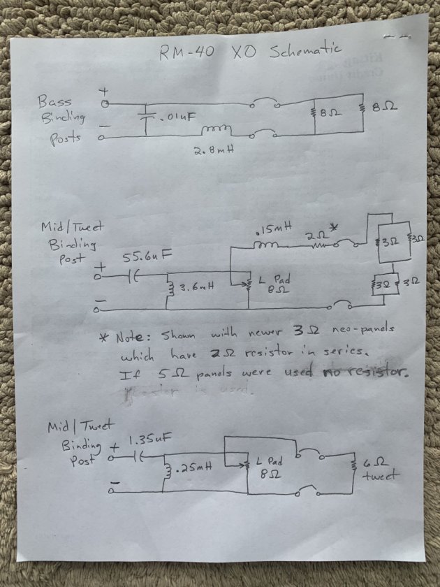
RM-40 Schematic. Two sets of parrallel neo-panels are in series. Woofers are in parallel.
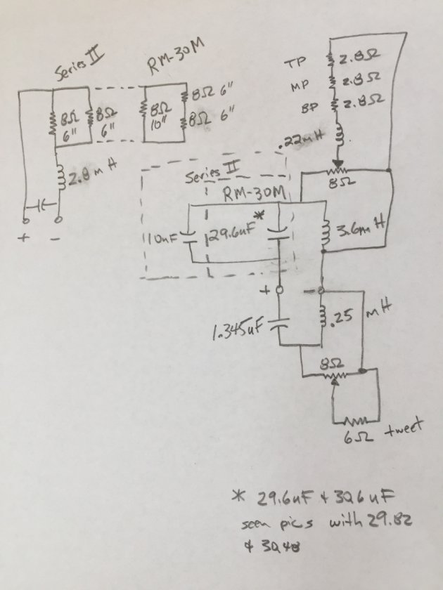
 RM-30 Schematic.
 Neo panels are all in series. Series 2 woofers are in parrallel. For M series 10" driver is in parrallel with two series 6.5" drivers.
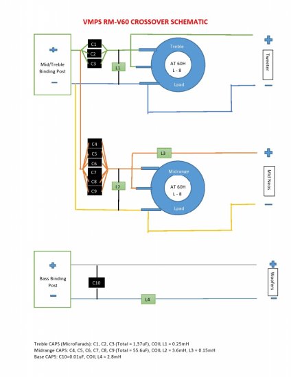
 RM-60 Schematic.
 Three sets of parrallel neo-panels are in series. For low bass section, forward fring woofer is in parrallel with two side drivers that are in series (looks similar to RM-30 M series shown in schematic).
 626 Schematic.
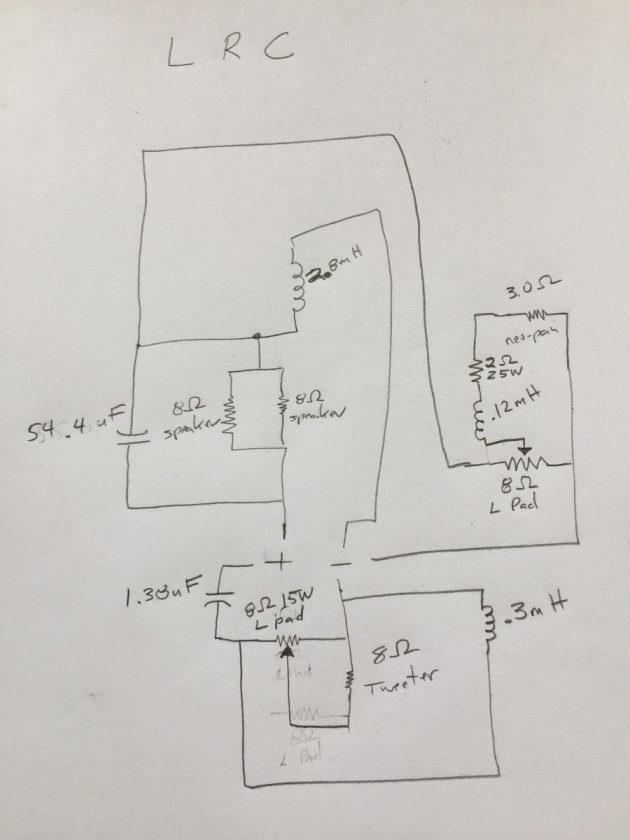
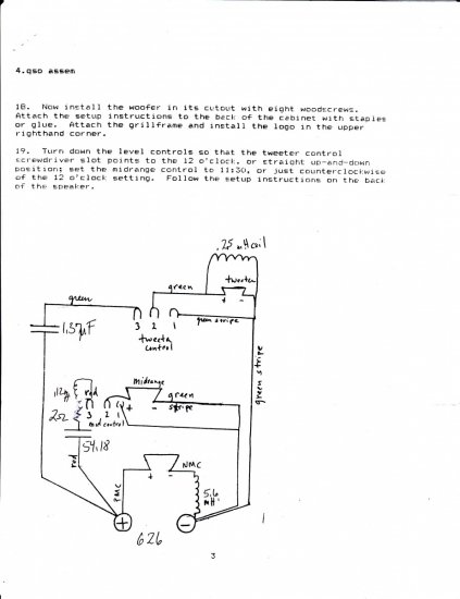 LRC Schematic: