Vintage 1996 AVA Omega III repair

0 Members and 1 Guest are viewing this topic. Read 1471 times.

Briansilcox

  • Jr. Member
  • Posts: 17
Vintage 1996 AVA Omega III repair
« on: 19 Apr 2023, 04:54 pm »
Hello...

Just signed in first time, I am interested in vintage tube and solid state power amps, learning to troubleshoot and repair, purely for my own use.  I started in the 1970s building a Dynaco ST 120, PAT-4,  more recently built a VTA 120 kit, then completely tore down a Dynaco ST 400 this winter, applying Fantasia output boards and Dan Joffe power supply, with all new output transistors.   Great sounding amp!

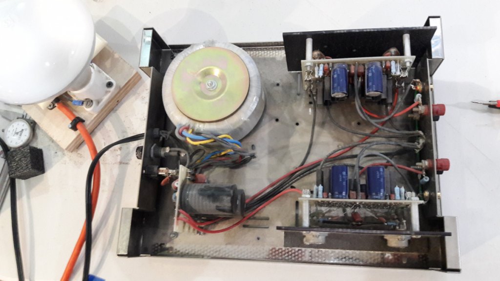
Recently acquired an AVA Omega 3 amp (Dynaco ST120 chassis) with toroidal power transformer.  Have begun initial assessments.  Previous owner reported “needs work.”  Powers up safely, B+/- reads 49v, assume power supply is good.

As I have had no luck online finding reference data or schematics, hoping for some input here.  I checked DC offset and idle bias current on each channel, but am reluctant to start any work without refs.

In the que, I have a nice running early Hafler DH 500, looking at Musical Concepts upgrades at some point.

Thank you, looking forward to spending some time here!

Brian

« Last Edit: 26 Oct 2023, 03:57 am by Briansilcox »

avahifi

Re: New member
« Reply #1 on: 19 Apr 2023, 08:16 pm »
Output of the power supply should be 90V DC.

Maybe has the 240V power transformer?

That, run on US 120V, would produce 45V Dc

Briansilcox

  • Jr. Member
  • Posts: 17
Re: New member
« Reply #2 on: 20 Apr 2023, 01:08 am »
Ok, thank you, sounds pretty plausible.  Power cord is std non polar two prong, but I can do a bit of research on the transformer part number.

Briansilcox

  • Jr. Member
  • Posts: 17
Re: New member
« Reply #3 on: 20 Apr 2023, 04:21 pm »
Thank you Frank,

Took another run at it.  The Plitron labeled 117vac.  Double checked voltage at the fuse to verify variac at 120v.  This time without dim bulb measured power supply +/- 58 volt dc.

The AC across the diode block compares with your expectation at 86vac.

So concentrating on the power supply, I should be seeing 90vdc output, but only getting 58vdc means issue with power supply itself?

danielgk

  • Jr. Member
  • Posts: 73
  • AVA engineer/technicion
Re: New member
« Reply #4 on: 20 Apr 2023, 05:10 pm »
You need to figure out whether this amp uses a plus and minus power supply (in which case your readings are probably right and the power supply is working properly). or a single positive supply (typically around 90vdc).  The lack of large coupling capacitors, and two (not one) large capacitors on the power supply board, leads me to believe its a + / - supply and should be in the ballpark of +/- 50 vdc.


Dan

Briansilcox

  • Jr. Member
  • Posts: 17
Re: New member
« Reply #5 on: 20 Apr 2023, 05:57 pm »
Thanks Dan,  agreed, it is definitely a +/- voltage supply.  Might be a little hard to see, but there are two 6.8k uf caps with a ground bus between them. 

I measured the caps this morning, showing 9k uf (in circuit) and the only other items in the circuit outside of the diode block are two 10k resistors one each from the + and - end to the center (gnd).  These measured only 500 ohms (in circuit) but I am not ready to de solder anything yet.

Briansilcox

  • Jr. Member
  • Posts: 17
Re: New member
« Reply #6 on: 20 Apr 2023, 06:16 pm »
Here’s both sides of the board.  The gray red pair connect to the diode block.  Pretty straightforward.


avahifi

Re: New member
« Reply #7 on: 22 Apr 2023, 08:32 pm »
Dan was correct.  I thought you had an earlier version that did use a +90V single ended supply.

Plus and minus 45V is correct for yours.

Frank
« Last Edit: 23 Apr 2023, 12:24 pm by avahifi »

Briansilcox

  • Jr. Member
  • Posts: 17
Re: New member
« Reply #8 on: 24 Apr 2023, 04:42 pm »
Thank you very much Frank! 

I am guessing this was built mid 1980s, so based upon age alone, planning to replace caps on the power supply and amp boards.  I suspect this may solve the “thunder claps” the previous owner complained about in one channel.

Brian

avahifi

Re: New member
« Reply #9 on: 24 Apr 2023, 07:27 pm »
Look what I found.  :)

The complete schematic from 1996 for our Omega III amplifier series.


If this is too blurry for you, email me and I can send you a higher resolution .pdf version.

Most common failure points were the solder connections to the left side (on the schematic) of the 2N3440 and 2N5416 finned transistors.  These could cook the connections between their leads and the foil traces over the years.
desoldering these six connections usually fixes the amplifier.

The electrolytic capacitors in those amps seemed to last forever so don't replace any that have not failed.

Frank

Briansilcox

  • Jr. Member
  • Posts: 17
Re: New member
« Reply #10 on: 24 Apr 2023, 09:10 pm »
Frank,

Thank you so much... that will help enormously!   I will send you an email.

Brian

Briansilcox

  • Jr. Member
  • Posts: 17
Re: New member
« Reply #11 on: 25 Apr 2023, 04:47 am »
Frank,

From the schematic notes, my power supply should be 56v (measured 58.6), as I have the 2.0K Ohm resistors.   As you pointed out, the 1000uF 63v and 100uF 63v caps checked out very well with low ESR.  Very impressive.  I did reflow the connections on the 2N5416 and 2N3440, so that possibility should be eliminated.

Some fresh compound and reassembly, should tell the story...  thanks for guidance!

Brian

Briansilcox

  • Jr. Member
  • Posts: 17
Re: New member
« Reply #12 on: 4 May 2023, 07:19 pm »
Have made some progress on this project.  After testing all of the electrolytic caps, finding all at spec, with very good esr values.  Per Frank’s recommendation, reflowed all the finned transistor leads.  Had to replace silica heatsink pads, as one flaked off in pieces.

With reassembly complete, found the problematic left channel bias idle current now stable at 163mA, and the right channel still stable at 168mA.

I have 2SK133 and 2SJ48 mosfet pairs... am I correct reading the above schematic note to set the idle bias current at 175mA measured across the positive fuse holder?

Thank you,

Brian


danielgk

  • Jr. Member
  • Posts: 73
  • AVA engineer/technicion
Re: New member
« Reply #13 on: 4 May 2023, 07:56 pm »
That sounds WAY too high.  Try 55ma and see if you can detect any audio difference - I bet you can't.  It will run a lot cooler and the noise at idle will be reduced substantially.


Dan

Briansilcox

  • Jr. Member
  • Posts: 17
Re: New member
« Reply #14 on: 4 May 2023, 08:40 pm »
Thanks Dan... will try that.

 Curious, about how I should interpret last line in schematic note “75mA +100mA per 2sk135 device, or +75mA per 2sj76 device”

I did just run the amp with audio input for the first time, thought it sounded very good, running for about 1/2 hour at 80% power.   I will readjust to 55mA and report back.


Briansilcox

  • Jr. Member
  • Posts: 17
Re: New member
« Reply #15 on: 4 May 2023, 10:02 pm »
Dan,

I adjusted bias slowly, was only able to reach 77/74 mA when the pots reached its lower limit.  Let each channel stand for 10 mins to allow for any temp reaction to the adjustment. 

danielgk

  • Jr. Member
  • Posts: 73
  • AVA engineer/technicion
Re: New member
« Reply #16 on: 5 May 2023, 11:14 am »
On the current AVA amps the bias is set to around 55 ma.  The lowest we can get to is around 25ma.  This 25ma is what the audio amp takes with the mosfets completely off.  At this point there is a lot of crossover distortion visible on an oscilloscope, and this would be a class B amplifier, not class AB.  The bias is increased by turning all mosfets on.  The more you turn them on, the more bias current flows.  All crossover distortion disappears around 30ma, and we set the bias at a substantial amount above that: 55ma (between 50-60).  Now solidly into class AB.

Your amp must require 74-77 ma with all mosfets off.  If you has an oscilloscope, you would probably see crossover distortion that goes away as you increase the bias to 80-85ma.  I'd set your bias to somewhere between 100-110 ma.  This is quite a bit lower than the 175ma on the schematic note and should result in lower operating temperature, lower noise, and no other noticeable differences. 


Dan

Briansilcox

  • Jr. Member
  • Posts: 17
Re: New member
« Reply #17 on: 5 May 2023, 02:20 pm »
Ok... that sounds like a good plan.  When I ran it at 77mA, I could not really hear a difference, but I do understand the crossover distortion issue..  When I reset the bias to 150mA, I must say that this amp really sounds good to me, terrific bass, and very quiet.  Definitely worth the effort to revive it.

Will let you know, and thanks again...   oscilloscope is coming soon.

Brian

Briansilcox

  • Jr. Member
  • Posts: 17
Re: New member
« Reply #18 on: 5 May 2023, 08:34 pm »
Dan,

I have set the bias now at 105mA, and will leave it there until I have the oscilloscope to fine tune it. 

I did have a residual crackling in the right channel, but discovered the source... one of the small finned transistors... by nudging it I could silence the crackling.  Frank had pointed out this possibility, even though I had reflowed all of the finned transistors leads, this one required a little extra effort.

Now the amp is dead quiet, and in particular, truly an excellent sounding amplifier.  Please pass along my thanks to Frank for providing reference schematic, and support, and thank you for your help!

Brian

Briansilcox

  • Jr. Member
  • Posts: 17
Re: New member
« Reply #19 on: 6 May 2023, 02:07 pm »
With gracious assistance of both Daniel and Frank of AVA hifi, this AVA Omega III amplifier has project has come to a successful conclusion.  After several hours listening, this compact design really delivers a fine reproduction quality, and proved to be well worth the effort to restore.